

NTE NTE6234 Datasheet

NTE6234
Powerblock Module
Description:
The NTE6234 u s es 2 high voltage power diodes in series and the semiconductors a re electrically
isolated f rom the m etal base, a l lowing common h eatsi nks a nd compact assemblies t o be b uilt. This
device is i ntended for general purpose applications such as battery chargers, welders and pl ati ng
equipment and where high voltage and high current are required.
Features:
D High Voltage
D Electrically Isolated Base Plate
D 3000V
D High Surge Capability
D Large Creepage Distances
Ratings and Characteristics:
Average Forward Current (TC = +100°C, 180° Conduction, Half Sine Wave), I
Maximum RMS Forward Current (As AC Switch), I
Maximum Repetitive Peak Reverse Voltage, V
Maximum Non–Repetitive Peak Reverse Voltage, V
Maximum Peak Reverse Current (TJ = +150°C), I
RMS Isolation Voltage (50Hz, Circuit to Base, All Terminals Shorted, t = 1s), V
Operating Junction Temperature Range, T
Storage Temperature Range, T
Thermal Resistance, Junction–to–Case (Per Module, DC Operation), R
Thermal Resistance, Case–to–Sink (Per Module, Note 1), R
Isolating Voltage
RMS
stg
F(AV)
T(RMS)
RRM
RSM
RRM
ISO
J
–40° to +150°C. . . . . . . . . . . . . . . . . . . . . . . . . . . . . . . . . .
195A. . . . . . . . .
305A. . . . . . . . . . . . . . . . . . . . . . . . . . . . . . .
1600V. . . . . . . . . . . . . . . . . . . . . . . . . . . . . . . . . . .
1700V. . . . . . . . . . . . . . . . . . . . . . . . . . . . . . .
50mA. . . . . . . . . . . . . . . . . . . . . . . . . . . . . . . . .
3000V. . . . . . . .
–40° to +150°C. . . . . . . . . . . . . . . . . . . . . . . . . . . . . . . . . . . . . . . . . .
thJC
thCS
0.20°C/W. . . . . . . . . . .
0.035°C/W. . . . . . . . . . . . . . . . . . .
Note 1. Mounting surface flat, smooth and greased.
Electrical Specifications:
Parameter Symbol Test Conditions Rating Unit
Maximum Peak One–Cycle I
Non–Repetitive Surge Current
FSM
t = 10ms
t = 8.3ms
t = 10ms
t = 8.3ms
Sinusoidal Half Wave, 100% V
Reapplied, Initial TJ = +150°C
Sinusoidal Half Wave, No Voltage
Reapplied, Initial TJ = +150°C
RRM
4000 A
4200 A
4750 A
4980 A
Electrical Specifications (Cont’d):
Parameter Symbol Test Conditions Rating Unit
Maximum I2t for Fusing I2t
Maximum I2pt I2pt
Threshold Voltage, Low level V
Threshold Voltage, High level V
Forward Slope Resistance, Low Level r
Forward Slope Resistance, High Level r
Maximum Forward Voltage Drop V
F(TO)1TJ
F(TO)2TJ
f1
f2
FM
AC
t = 10ms
t = 8.3ms
t = 10ms
t = 8.3ms
Sinusoidal Half Wave, 100% V
RRM
Reapplied, Initial TJ = +150°C
Sinusoidal Half Wave, No Voltage
Reapplied, Initial TJ = +150°C
80 kA2s
73 kA2s
113 kA2s
103 kA2s
t = 0.1 to 10ms, no voltage reapplied 1 130
= +150°C, (16.7% x π x I
= +150°C, (π x I
< I < 20 x π x I
T(AV)
TJ = +150°C, (16.7% x π x I
TJ = +150°C, (π x I
TJ = +25°C, IFM = π x I
Av. Power = V
F(TO)
< I < 20 x π x I
T(AV)
F(AV)
x I
T(AV)
< I < π x I
T(AV)
< I < π x I
T(AV)
,
+ rf x (I
T(AV)
T(AV)
F(RMS)
) 0.75 V
T(AV)
) 0.86 V
) 0.92 mΩ
T(AV)
) 0.77 mΩ
1.32 V
2
)
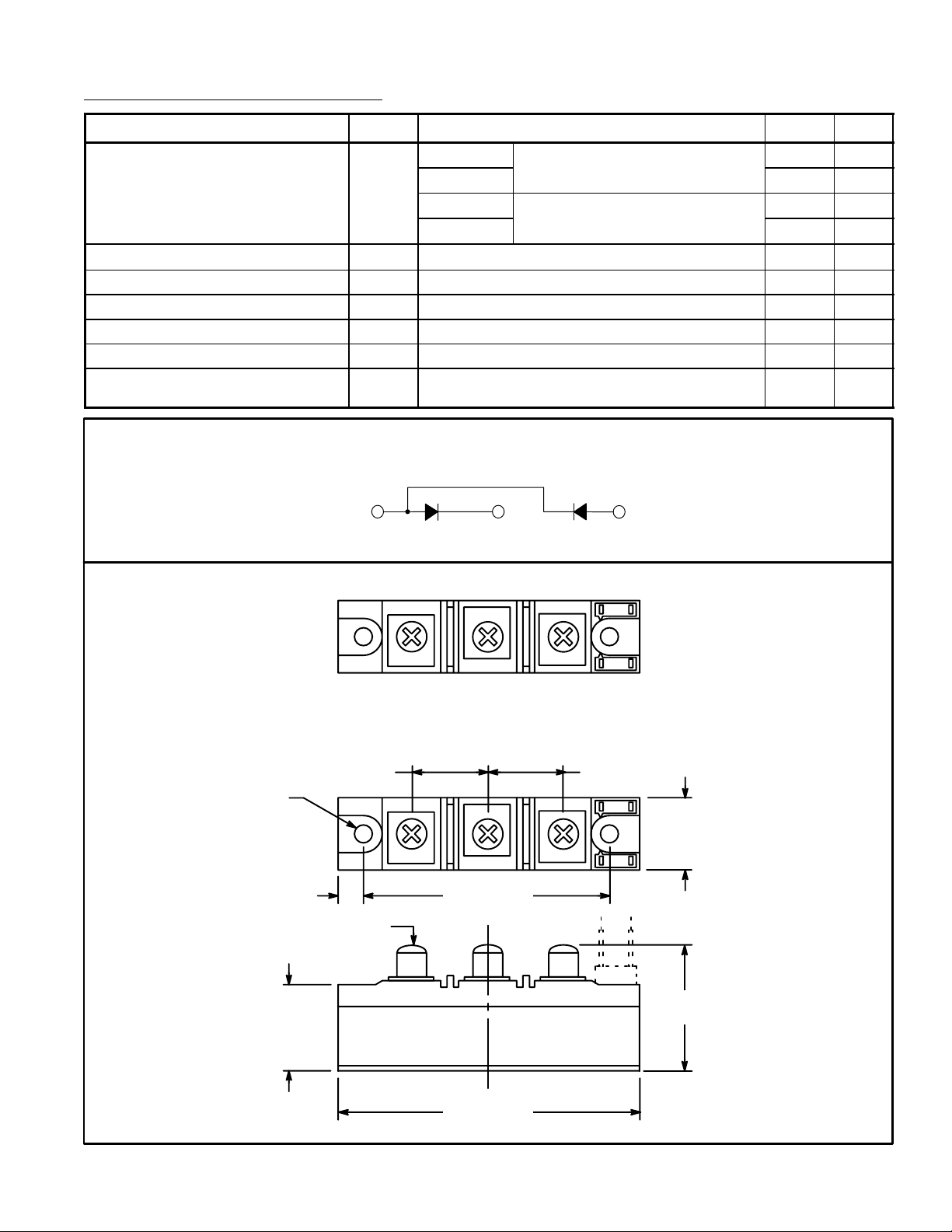
Circuit Diagram
+ –
K2 G2
+
kA2pt
.244 (6.2) Dia
(2 Places)
.270 (7.0)
M6 x 1 Screw (3 Places)
1.180
(30.0)
AC
.980 (25.0) .980 (25.0)
3.150 (80.0)
–
K1 G1
1.340
(34.0)
1.850
(47.0)
3.700 (94.0)
 Loading...