

NTE NTE6090 Datasheet
NTE6090
Silicon Dual Power Rectifier
Description:
The NTE6090 is a silicon dual power rectifier in a TO3P/TO218 type package designed using the
Schottky Barrier principle with a platinum barrier metal.
Features:
D Dual Diode Construction: Pin1 and Pin3 may be Connected for Parallel Operation at Full Range
D Guarding for Stress Protection
D Low Forward Voltage
D +150°C Operating Junction Temperature
D Guaranteed Reverse Avalanche
Absolute Maximum Ratings:
Peak Repetitive Reverse Voltage, V
Working Peak Reverse Voltage, V
DC Blocking Voltage, V
R
Average Rectified Forward Current (VR = 45V, TC = +105°C), I
RRM
RWM
F(AV)
Per Device 30A. . . . . . . . . . . . . . . . . . . . . . . . . . . . . . . . . . . . . . . . . . . . . . . . . . . . . . . . . . . . . . . . . .
Per Diode 15A. . . . . . . . . . . . . . . . . . . . . . . . . . . . . . . . . . . . . . . . . . . . . . . . . . . . . . . . . . . . . . . . . . .
Peak Repetitive Forward Current, Per Diode (VR = 45V, Square Wave, 20kHz), I
Non–Repetitive Peak Surge Current, I
FSM
FRM
(Surge Applied at Rated Load Conditions, Halfwave, Single Phase, 60Hz) 200A. . . . . . . . . .
Peak Repetitive Reverse Current, Per Diode (2µs, 1kHz), I
Operating Junction Temperature Range, T
Storage Temperature Range, T
stg
J
Peak Surge Junction Temperature (Forward Current Applied), T
RRM
–65° to +150°C. . . . . . . . . . . . . . . . . . . . . . . . . . . . . . . . . .
–65° to +175°C. . . . . . . . . . . . . . . . . . . . . . . . . . . . . . . . . . . . . . . . . .
J(pk)
Voltage Rate of Change (VR = 45V), dv/dt 1000V/µs. . . . . . . . . . . . . . . . . . . . . . . . . . . . . . . . . . . . . . . .
Thermal Resistance, Junction–to–Case, R
Thermal Resistance, Junction–to–Ambient, R
thJC
thJA
45V. . . . . . . . . . . . . . . . . . . . . . . . . . . . . . . . . . . . . . . . . . . . . . .
45V. . . . . . . . . . . . . . . . . . . . . . . . . . . . . . . . . . . . . . . . . . . . . . . .
45V. . . . . . . . . . . . . . . . . . . . . . . . . . . . . . . . . . . . . . . . . . . . . . . . . . . . . . . . . . . .
30A. . . . . . . .
2A. . . . . . . . . . . . . . . . . . . . . . . . . . . .
+175°C. . . . . . . . . . . . . . . . . . .
1.4°C/W. . . . . . . . . . . . . . . . . . . . . . . . . . . . . . . . . . . . .
40°C/W. . . . . . . . . . . . . . . . . . . . . . . . . . . . . . . . . . . .
Electrical Characteristics (Per Diode): (Note 1)
Parameter Symbol Test Conditions Min Typ Max Unit
Instantaneous Forward Voltage v
Instantaneous Reverse Current i
iF = 20A, TC = +125°C – – 0.60 V
F
iF = 30A, TC = +125°C – – 0.72 V
iF = 30A, TC = +25°C – – 0.76 V
VR = 45V, TC = +125°C – – 100 mA
R
VR = 45V, TC = +25°C – – 1 mA
Note 1. Pulse Test: Pulse Width = 300µs, Duty Cycle ≤ 2%.
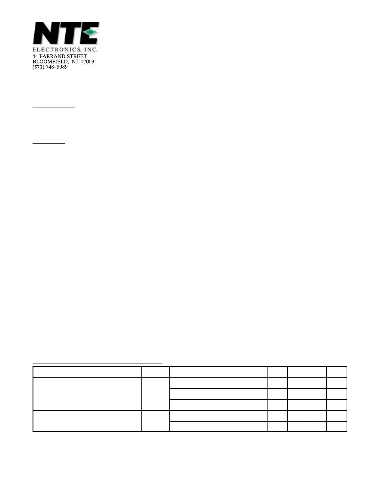
.787
(20.0)
TO3P Type Package
.615 (15.62).190 (4.82)
K
.591
(15.02)
.787
(20.0)
AKA
.126 (3.22)
Dia
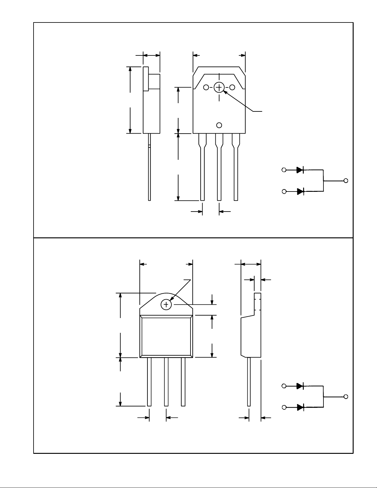
.815
(20.72)
.500
(12.7)
Min
TO218 Type Package
.626 (15.92)
Max
.166 (4.23)
Dia Max
K
A1 K A2
.215 (5.47)
.200 (5.08)
Max
.050
(1.27)
.147 (3.76)
.490
(12.44)
.215 (5.47)
.110 (2.79)
 Loading...