

NTE NTE6013 Datasheet

NTE6013
Silicon Industrial Rectifier
20 Amp
Description:
The NTE6013 is a 20 Ampere (RMS) silicon rectifier in an electrically isolated TO220 type package
with a voltage rating of 600V for use in common anode or common cathode circuits. This device features a glass–passivated junction to ensure long term reliability and stability. In addition, glass offers
a rugged, reliable barrier against junction contamination.
Features:
D Electrically–Isolated Package
D High Voltage Capabilities: V
D High Surge Capabilities (Up to 300 Amps)
D Glass–Passivated Junction
RRM
= 600V
Electrical Specifications:
Minimum Peak Repetitive Reverse Voltage, V
Minimum DC Blocking Voltage, V
Maximum Average Forward Current, I
Maximum RMS Forward Current, I
Peak One Cycle Surge Current, I
(Note 1)
R
F(RMS)
FSM
F(AV)
RRM
600V. . . . . . . . . . . . . . . . . . . . . . . . . . . . . . . . . . . . .
600V. . . . . . . . . . . . . . . . . . . . . . . . . . . . . . . . . . . . . . . . . . . . . . . . . .
12.7A. . . . . . . . . . . . . . . . . . . . . . . . . . . . . . . . . . . . . . . . . .
20A. . . . . . . . . . . . . . . . . . . . . . . . . . . . . . . . . . . . . . . . . . . . . .
60Hz 300A. . . . . . . . . . . . . . . . . . . . . . . . . . . . . . . . . . . . . . . . . . . . . . . . . . . . . . . . . . . . . . . . . . . . . .
50Hz 255A. . . . . . . . . . . . . . . . . . . . . . . . . . . . . . . . . . . . . . . . . . . . . . . . . . . . . . . . . . . . . . . . . . . . . .
Maximum Peak Reverse Current, I
RM
TC = +25°C 0.1mA. . . . . . . . . . . . . . . . . . . . . . . . . . . . . . . . . . . . . . . . . . . . . . . . . . . . . . . . . . . . . . . .
= +100°C 0.5mA. . . . . . . . . . . . . . . . . . . . . . . . . . . . . . . . . . . . . . . . . . . . . . . . . . . . . . . . . . . . . . .
T
C
T
= +125°C 1.0mA. . . . . . . . . . . . . . . . . . . . . . . . . . . . . . . . . . . . . . . . . . . . . . . . . . . . . . . . . . . . . . .
C
Maximum Peak Forward Voltage (V
= 600V, TC = +25°C), V
RRM
FM
RMS Surge (Non–Repetitive) Forward Current for 8.3mS for Fusing, I
Operating Temperature Range, T
Storage Temperature Range, T
Lead Temperature (During Soldering, 1/16” from case for 10sec), T
Typical Thermal Resistance (Steady State), Junction–to–Case, R
opr
stg
L
thJC
2
t 374A2Sec. . . . . . . . . . . . .
–40° to +125°C. . . . . . . . . . . . . . . . . . . . . . . . . . . . . . . . . . . . . . . .
–40° to +125°C. . . . . . . . . . . . . . . . . . . . . . . . . . . . . . . . . . . . . . . . . .
1.6V. . . . . . . . . . . . . . . . . . . . . .
+230°C. . . . . . . . . . . . . . . . . . .
2.5°C/W. . . . . . . . . . . . . . . . .
Note 1. TC = TJ for test conditions.
Note 2. Electrically isolated TO220 devices will withstand a high potential test of 2500VAC RMS from
leads to case over the operating temperature range.
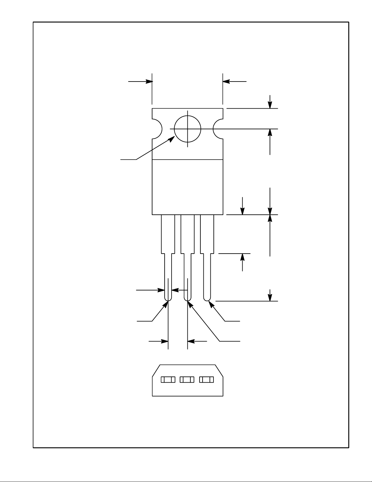
.147 (3.75)
Dia Max
.420 (10.67)
Max
.110 (2.79)
Tab/Isolated
.500
(12.7)
Max
.250 (6.35)
Max
.070 (1.78) Max
Cathode
.100 (2.54)
.500
(12.7)
Min
N.C.
Anode
 Loading...