

NTE NTE5904, NTE5911, NTE5909, NTE5908, NTE5901 Datasheet
...
NTE5892 thru NTE5899
NTE5900 thru NTE5911
Silicon Power Rectifier Diode, 16 Amp
Description and Features:
The NTE5892 through NTE5911 are low power general purpose rectifier diodes in a DO4 type package designed for battery chargers, converters, power supplies, and machine tool controls.
Features:
D High Surge Current Capability
D High Voltage Available
D Designed for a Wide Range of Applications
D Available in Anode–to–Case or Cathode–to–Case Style
Ratings and Characteristics:
Average Forward Current (TC = +140°C Max), I
Maximum Forward Surge Current, I
FSM
F(AV)
50Hz 295A. . . . . . . . . . . . . . . . . . . . . . . . . . . . . . . . . . . . . . . . . . . . . . . . . . . . . . . . . . . . . . . . . . . . . .
60Hz 310A. . . . . . . . . . . . . . . . . . . . . . . . . . . . . . . . . . . . . . . . . . . . . . . . . . . . . . . . . . . . . . . . . . . . . .
Fusing Current, I2t
50Hz 435A2s. . . . . . . . . . . . . . . . . . . . . . . . . . . . . . . . . . . . . . . . . . . . . . . . . . . . . . . . . . . . . . . . . . . .
60Hz 395A2s. . . . . . . . . . . . . . . . . . . . . . . . . . . . . . . . . . . . . . . . . . . . . . . . . . . . . . . . . . . . . . . . . . . .
Fusing Current, I2pt 6150A2ps. . . . . . . . . . . . . . . . . . . . . . . . . . . . . . . . . . . . . . . . . . . . . . . . . . . . . . . . .
Maximum Reverse Recovery Voltage Range, V
RRM
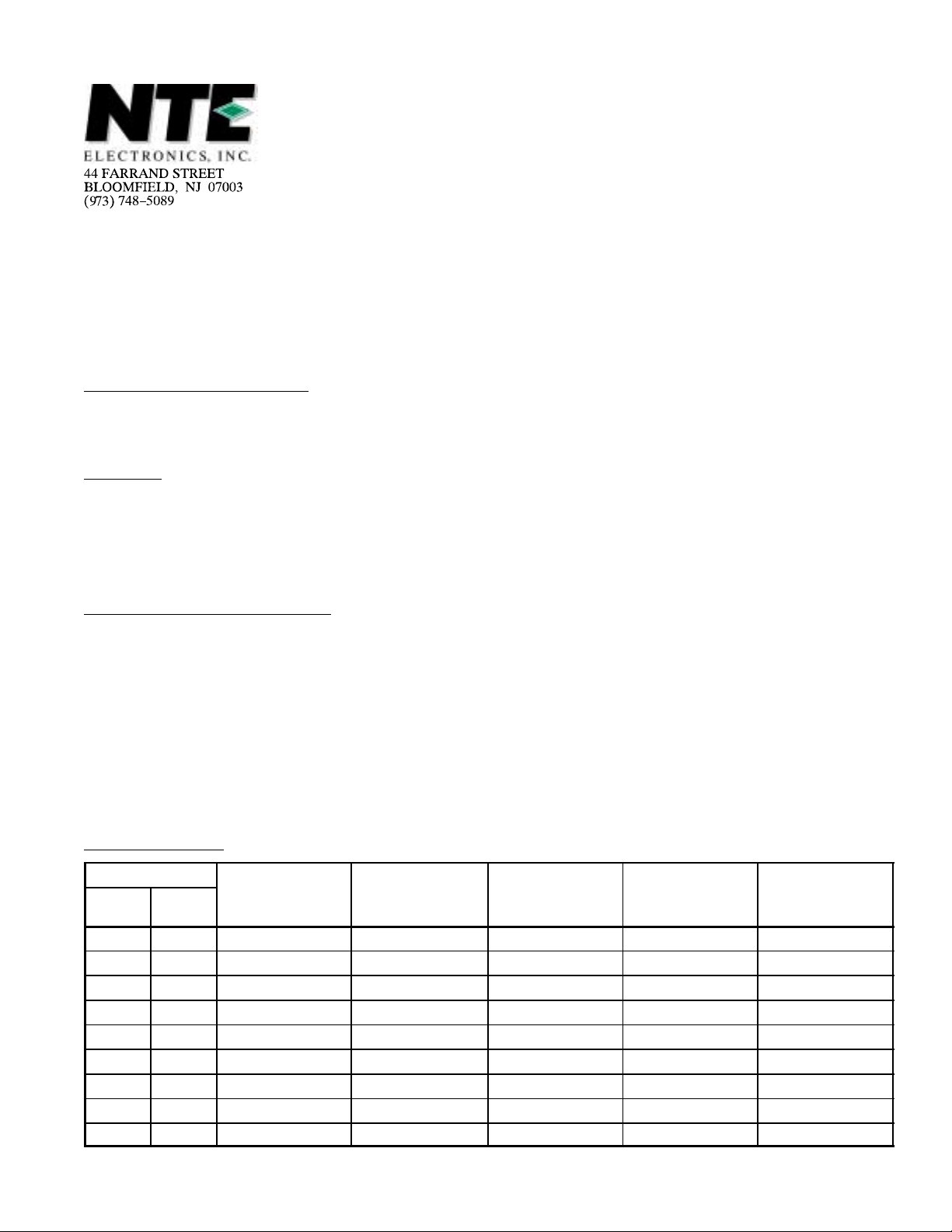
Voltage Ratings: (TJ = +175°C)
V
NTE Type Number
Cathode
to Case
Anode
to Case
–Max V
RRM
Repetitive Peak
Reverse Volt.
(V)
Non–Repetitive Peak
Reverse Voltage
5892 5893 50 75 50 – 12
5894 5895 100 150 100 – 12
5896 5897 200 275 200 – 12
5898 5899 300 385 300 – 12
5900 5901 400 500 400 500 12
5902 5903 500 613 50 626 12
5904 5905 600 725 600 750 12
5908 5909 800 950 800 950 12
5910 5911 1000 1200 1000 1150 12
–Max VR–Max. V
RSM
(V)
Direct Reverse
Voltage
(V)
Minimum Avalanche
R(SR)
Voltage
(V)
Reverse Current
50 to 1000V. . . . . . . . . . . . . . . . . . . . . . . . . . . . . .
IRM–Max
Rated V
(mA)
16A. . . . . . . . . . . . . . . . . . . . . . . . . . . . . . . . . . . .
RRM
Electrical Specifications:
Parameter Symbol Test Conditions Rating Unit
Maximum Average Forward Current I
Maximum RMS Forward Current I
Maximum Peak One–Cycle I
F (AV)
F(RMS)
FSM
Non–Repetitive Surge Current
Maximum I2t for Individual Device I2t
Fusing
Maximum I2pt I2pt
Maximum Peak Forward Voltage V
Maximum Value of Threshold
FM
V
M (TO)TJ
Voltage
Maximum Value of Forward Slope
r
t
Resistance
Note 1. I2t for time tx = I2Ǩt S Ǩt
x
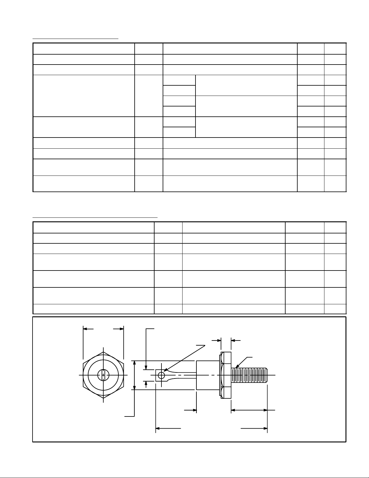
Thermal–Mechanical Specifications:
Parameter Symbol Test Conditions Rating Unit
180° sinusoidal condition, TC = +140°C Max 16 A
25 A
t = 10ms
t = 8.3ms
t = 10ms
t = 8.3ms
t = 10ms
t = 8.3ms
Sinusoidal Half Wave,
No voltage reapplied
100% rated voltage reapplied,
TJ = +175°C
100% rated voltage reapplied,
Initial TJ = +175°C
t = 0.1 to 10ms, No voltage reapplied, Note 1 6125
295 A
310 A
350 A
370 A
612 A2s
560 A2s
A2pt
IFM = 50A, TJ = +25°C 1.23 V
= +175°C 0.78 V
TJ = +175°C 7.55 mΩ
Maximum Operation Junction Temperature T
Maximum Storage Temperature T
Maximum Internal Thermal Resistance
R
J
stg
thJC
DC operation 1.6 K/W
–65 to + 175 °C
–65 to + 200 °C
Junction–to–Case
Thermal Resistance, Case–to–Sink R
thCS
Mounting surface flat, smooth and
0.5 K/W
greased
Mounting Torque T Non–lubricated threads 1.2 – 1.5
(10.5 – 13.5)
m•N
(in•lb)
Approximate Weight wt 11 (0.25) g (oz)
.437
.250 (6.35) Max
(11.1)
Max
.060 (1.52)
.175 (4.45) Max
Dia Min
10–32 NF–2A
.405
.424 (10.8)
Dia Max
(10.3)
Max
1.250 (31.75) Max
.453
(11.5)
Max
 Loading...