

NTE NTE571 Datasheet
NTE571
General Purpose Silicon Rectifier
Fast Switching, Soft Recovery
Absolute Maximum Ratings:
Repetitive Peak Reverse Voltage, V
Continuous Reverse Voltage, V
Average Forward Rectified Current, I
.394” (10mm) lead length, Ttp = +55°C 2.9A. . . . . . . . . . . . . . . . . . . . . . . . . . . . . . . . . . . . . . . .
T
= +65°C 1.2A. . . . . . . . . . . . . . . . . . . . . . . . . . . . . . . . . . . . . . . . . . . . . . . . . . . . . . . . . . . . . . . . .
A
Repetitive Peak Forward Current, I
Ttp = +55°C 33A. . . . . . . . . . . . . . . . . . . . . . . . . . . . . . . . . . . . . . . . . . . . . . . . . . . . . . . . . . . . . . . . .
TA = +65°C 11A. . . . . . . . . . . . . . . . . . . . . . . . . . . . . . . . . . . . . . . . . . . . . . . . . . . . . . . . . . . . . . . . . .
Non–Repetitive Peak Forward Current, I
t = 10ms, half sine–wave, TJ = +175°C prior to surge, VR = 1000V 65A. . . . . . . . . . . . . . . . . .
Non–Repetitive Peak Reverse Avalanche Energy, E
IR = 400mA, TJ = +175°C prior to surge; with inductive load off 10mJ. . . . . . . . . . . . . . . . . . .
Operating Junction Temperature Range, T
Storage Temperature Range, T
Thermal Resistance, Junction–to–tie point (10mm lead lenght), R
Thermal Resistance, Junction–to–Ambient, R
Mounted on 1.5mm thick PC Board, Cu–thickness > 40µm 75K/W. . . . . . . . . . . . . . . . . . . . .
RRM
R
F(AV)
FRM
FSM
RSM
J
stg
thja
thj0tp
1000V. . . . . . . . . . . . . . . . . . . . . . . . . . . . . . . . . . . . . . . . . . . . .
1000V. . . . . . . . . . . . . . . . . . . . . . . . . . . . . . . . . . . . . . . . . . . . . . . . . . .
–65° to +175°C. . . . . . . . . . . . . . . . . . . . . . . . . . . . . . . . . .
–65° to +175°C. . . . . . . . . . . . . . . . . . . . . . . . . . . . . . . . . . . . . . . . . .
25K/W. . . . . . . . . . . . . . . . .
Electrical Characteristics:
Parameter Symbol Test Conditions Min Typ Max Unit
Forward Voltage Drop V
Reverse Avalanche Breakdown Voltage V
Reverse Current I
Reverse Recovery Time t
(TJ = +25°C unless otherwise specified)
IF = 3A, T
F
IF = 3A, Note 1 – – 1.78 V
(BR)RIR
VR = 1000V – – 5 µA
R
VR = 1000V, TJ = +165°C – – 150 µA
when switched from
rr
I
measured at I
= 0.1mA – – 1100 V
= 0.5A to IR = 1A
F
= +175°C, Note 1
J
= 0.25A
R
Note 1. Measured under pulse conditions to avoid excessive dissipation.
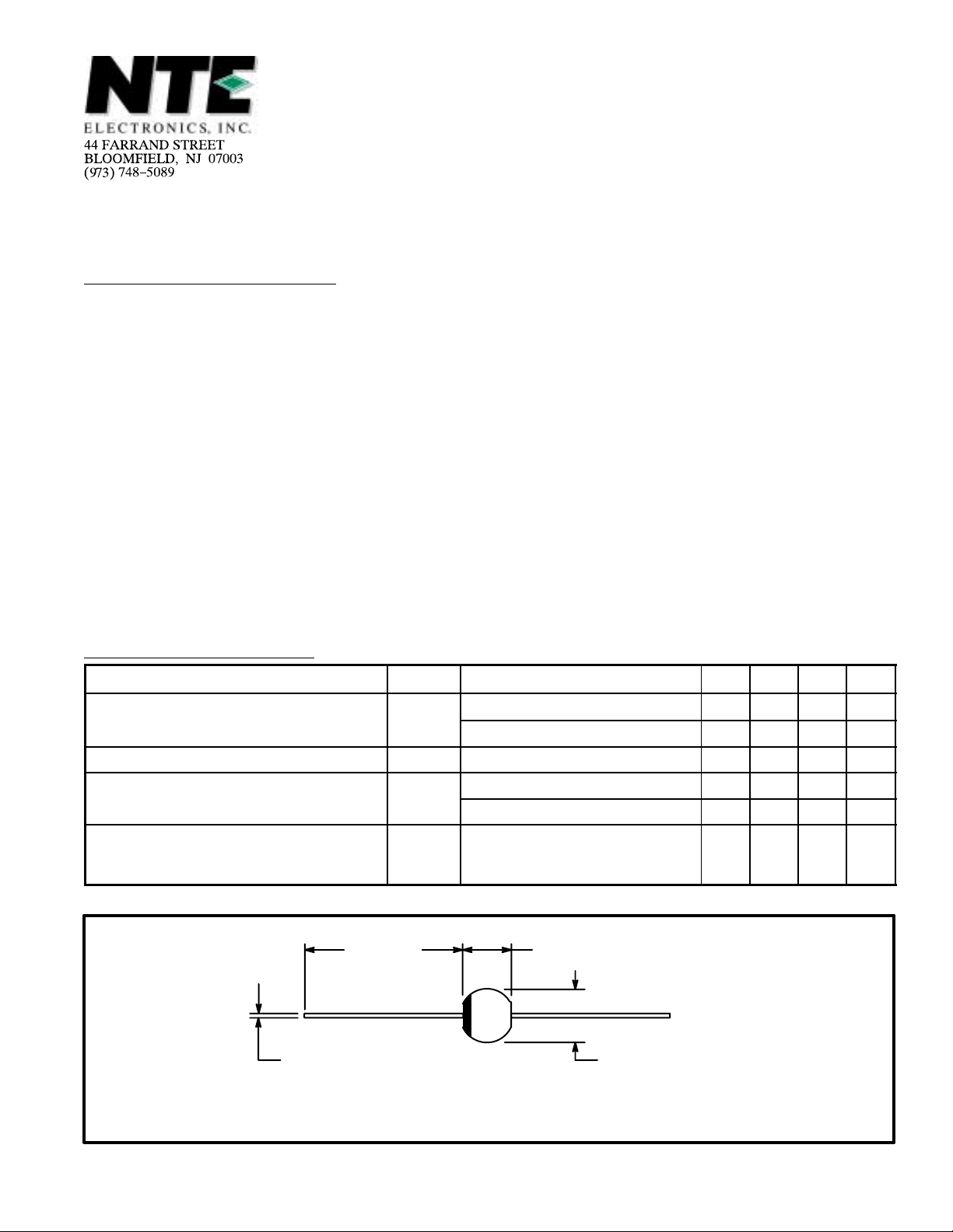
1.000
.165 (4.2) Max
(25.4)
Min
.053 (1.35) Dia Max
.169 (4.3) Max
– – 1.28 V
– – 150 ns
Color Band Denotes Cathode
 Loading...