

NTE NTE5680, NTE5686, NTE5685, NTE5683, NTE5681 Datasheet
...
NTE5680 thru NTE5687
TRIAC, 25 Amp
Description:
The NTE5680 thru NTE5687 series of medium power TRIACs are bidirectional triode thyristors which
may be switched from off–state to conduction for either polarity of applied voltage with positive or negative gate triggering. Theses devices are designed for control of AC loads in applications such as
lighting, heating, and motor speed control, as well as static switching relays.
Absolute Maximum Ratings:
Repetitive Peak Off–State and Reverse Voltage (TJ = +100°C), V
DRM
, V
RRM
NTE5680 25V. . . . . . . . . . . . . . . . . . . . . . . . . . . . . . . . . . . . . . . . . . . . . . . . . . . . . . . . . . . . . . . . . . . .
NTE5681 50V. . . . . . . . . . . . . . . . . . . . . . . . . . . . . . . . . . . . . . . . . . . . . . . . . . . . . . . . . . . . . . . . . . . .
NTE5682 100V. . . . . . . . . . . . . . . . . . . . . . . . . . . . . . . . . . . . . . . . . . . . . . . . . . . . . . . . . . . . . . . . . . .
NTE5683 200V. . . . . . . . . . . . . . . . . . . . . . . . . . . . . . . . . . . . . . . . . . . . . . . . . . . . . . . . . . . . . . . . . . .
NTE5684 300V. . . . . . . . . . . . . . . . . . . . . . . . . . . . . . . . . . . . . . . . . . . . . . . . . . . . . . . . . . . . . . . . . . .
NTE5685 400V. . . . . . . . . . . . . . . . . . . . . . . . . . . . . . . . . . . . . . . . . . . . . . . . . . . . . . . . . . . . . . . . . . .
NTE5686 500V. . . . . . . . . . . . . . . . . . . . . . . . . . . . . . . . . . . . . . . . . . . . . . . . . . . . . . . . . . . . . . . . . . .
NTE5687 600V. . . . . . . . . . . . . . . . . . . . . . . . . . . . . . . . . . . . . . . . . . . . . . . . . . . . . . . . . . . . . . . . . . .
RMS On–State Current (TC = +75°C, 360° Conduction), I
T(RMS)
25A. . . . . . . . . . . . . . . . . . . . . . . . . .
Peak Surge (Non–Repetitive) On–State Current (One–Cycle, 50Hz or 60Hz), I
TSM
250A. . . . . . . .
Peak Gate–Trigger Current (3µs Max), I
GTM
4A. . . . . . . . . . . . . . . . . . . . . . . . . . . . . . . . . . . . . . . . . . . .
Peak Gate–Power Dissipation (IGT ≤ I
GTM
, 3µs Max), P
GM
40W. . . . . . . . . . . . . . . . . . . . . . . . . . . . . .
Average Gate Power Dissipation, P
G(AV)
0.8W. . . . . . . . . . . . . . . . . . . . . . . . . . . . . . . . . . . . . . . . . . . . .
Storage Temperature Range, T
stg
–40° to +150°C. . . . . . . . . . . . . . . . . . . . . . . . . . . . . . . . . . . . . . . . . .
Operating Temperature Range (TJ), T
opr
–40° to +100°C. . . . . . . . . . . . . . . . . . . . . . . . . . . . . . . . . . . . .
Thermal Resistance, Junction–to–Case, R
thJC
1.8°C/W. . . . . . . . . . . . . . . . . . . . . . . . . . . . . . . . . . . . .
Electrical Characteristics: (At Maximum Ratings, TA = +25°C unless otherwise specified)
Parameter Symbol Test Conditions Min Typ Max Unit
Peak Off–State Current I
DROM
Gate Open, IT = 100A (Peak) – – 4 mA
Maximum On–State Voltage V
T
IT = 100A (Peak) – – 2.5 V
DC Holding Current I
H
Gate Open – – 60 mA
Critical Rate–of–Rise of Off–State Voltage Critical
dv/dt
Gate Open, VD = Ra ted V
DROM
,
TC = +1 00°C
– 40 – V/µs
Critical Rate–of–Rise of Commutation Commutating
dv/dt
Gate Open, VD = Ra ted V
DROM
,
IT = 25A, TC = +7 5°C
– 3 – V/µs
DC Gate Trigger Current
MT2 (+), Gate (+); MT2 (–), Gate (–)
MT2 (+), Gate (–); MT2 (–), Gate (+)
I
GT
VD = 24V, RL = 12Ω –
–
––100
150mAmA
DC Gate Trigger Voltage V
GT
VD = 24V, RL = 12Ω – – 2.5 V
Gate–Controlled Turn–On Time t
gt
VD = Ra ted V
DROM
, IGT = 300mA,
tr = 0. 1µs, It = 10A
(Peak)
– 3 – µs
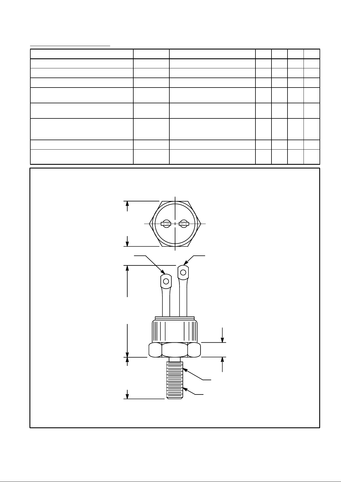
.200 (5.08) Max
.562
(14.28)
Max
.1.193
(30.33)
Max
.453
(111.5)
Max
1/4–28 UNF–2A
MT
2
MT
1
Gate
 Loading...