

NTE NTE5645 Datasheet
NTE5645
TRIAC – 10A
Isolated Tab
Description:
The NTE5645 is an 10 Amp TRIAC in a TO220 type package designed to be driven directly with IC
and MOS devices and features proprietary, void–free glass passivated chips.
This device is a bi–directional triode thyristor and may be switched from off–state to conduction for
either polarity of applied voltage with positive or negative gate trigger current. The NTE5645 is designed for control applications in lighting, heating, cooling and static switching relays.
Absolute Maximum Ratings:
Repetitive Peak Off–State Voltage (Gate Open, TJ = +100°C), V
RMS On–State Current (TC = +75°C, Conduction Angle of 180°C), I
DRM
T(RMS)
Peak Surge (Non–Repetitive) On–State Current (One Cycle, 50Hz or 60Hz), I
Peak Gate–Trigger Current (3µs Max), I
Peak Gate–Power Dissipation (IGT ≤ I
Average Gate–Power Dissipation, P
Operating Temperature Range, T
Storage Temperature Range, T
J
stg
Typical Thermal Resistance, Junction–to–Case, R
GTM
for 3µs Max), P
GTM
G(AV)
GM
thJC
TSM
–40° to +150°C. . . . . . . . . . . . . . . . . . . . . . . . . . . . . . . . . . . . . . . . . .
–40° to +100°C. . . . . . . . . . . . . . . . . . . . . . . . . . . . . . . . . . . . . . . . . .
600V. . . . . . . . . . . . . . . . . . . . .
10A. . . . . . . . . . . . . . . . .
100A. . . . . . . . .
4A. . . . . . . . . . . . . . . . . . . . . . . . . . . . . . . . . . . . . . . . . . . .
40W. . . . . . . . . . . . . . . . . . . . . . . . . . .
200mW. . . . . . . . . . . . . . . . . . . . . . . . . . . . . . . . . . . . . . . . . . .
2.5°C/W. . . . . . . . . . . . . . . . . . . . . . . . . . . . . .
Electrical Characteristics: (TC = +25°C, Maximum Ratings unless otherwise specified)
Parameter Symbol Test Conditions Min Typ Max Unit
Peak Off–State Current I
Max. On–State Voltage V
DC Holding Current I
Critical Rate–of–Rise of Off–State
Voltage
DC Gate Trigger Current
T2 (+) Gate (+), T2 (–) Gate (–)
T2 (+) Gate (–), T2 (–) Gate (+)
Critical
dv/dt
DRM
TM
H
I
GT
V
= 600V, Gate Open, TJ = +1 00°C – – 2 mA
DRM
IT = 14A – – 2.2 V
Gate Open – – 50 mA
VD = 600V, Gate Open, TC = +1 00°C – 5 – V/µs
VD = 12V, RL = 30Ω
–
––5080mA
–
mA
Electrical Characteristics (Cont’d): (TC = +25°C, Maximum Ratings unless otherwise specified)
Parameter Symbol Test Conditions Min Typ Max Unit
DC Gate Trigger Voltage V
Gate–Controlled Turn–On Time t
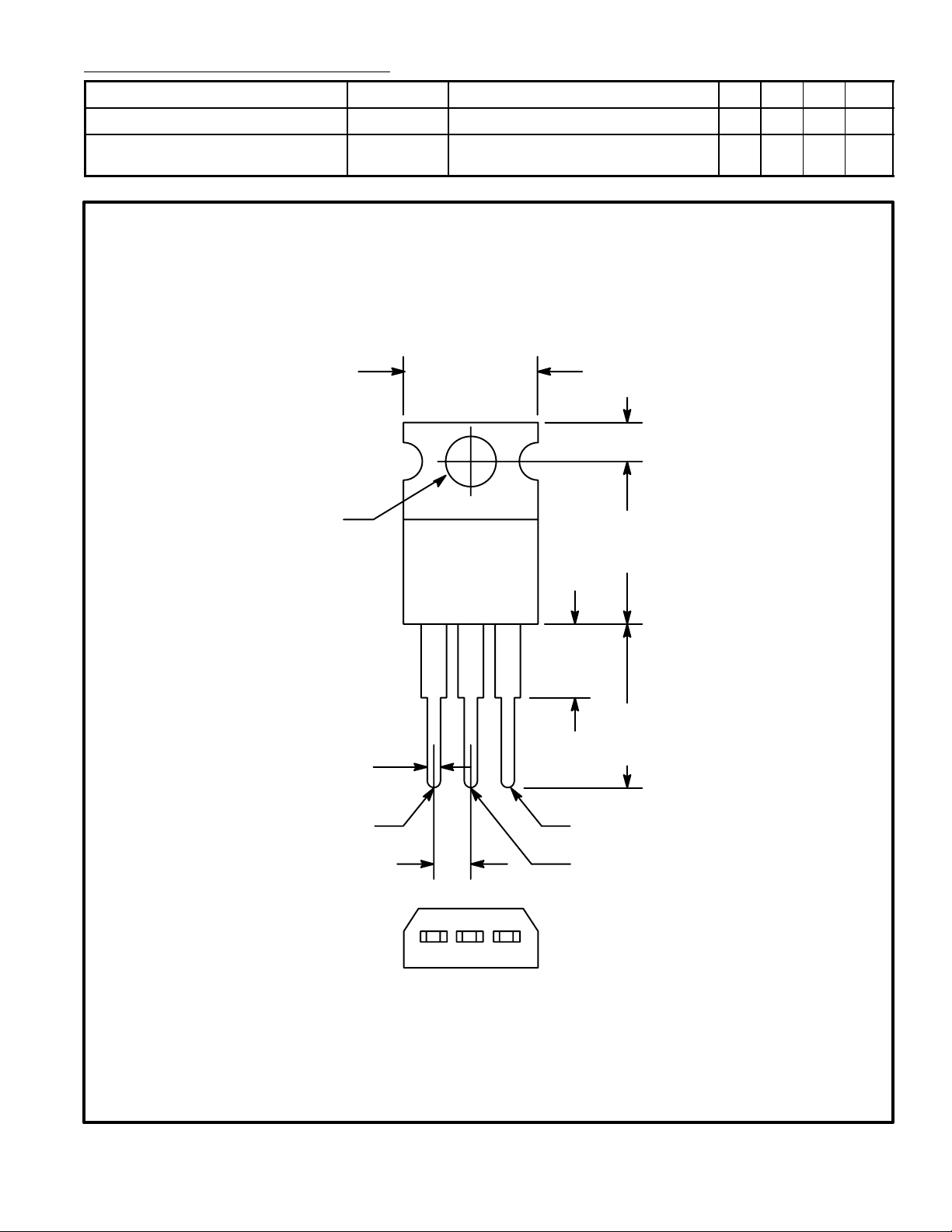
.147 (3.75)
Dia Max
GT
gt
VD = 12V, RL = 30Ω – – 2.5 V
VD = 600V, IGT = 80mA, tr = 0.1µs,
– 2.5 – µs
iT = 10A (Peak)
.420 (10.67)
Max
.110 (2.79)
Isolated
.500
(12.7)
Max
.070 (1.78) Max
MT
.100 (2.54)
.250 (6.35)
Max
.500
(12.7)
Min
1
Gate
MT
2
 Loading...