

NTE NTE519 Datasheet
Silicon Rectifier Diode
Absolute Maximum Ratings:
Repetitive Peak Reverse Voltage, V
Reverse Voltage, V
Surge Forward Current (t
Repetitive Peak Forward Current, I
Forward Current, I
Average Forward Current (V
Power Dissipation (I = 4mm), P
TL = +45°C 440mW. . . . . . . . . . . . . . . . . . . . . . . . . . . . . . . . . . . . . . . . . . . . . . . . . . . . . . . . . . . . . .
≤ +25°C 500mW. . . . . . . . . . . . . . . . . . . . . . . . . . . . . . . . . . . . . . . . . . . . . . . . . . . . . . . . . . . . . .
T
L
Junction Temperature, T
Storage Temperature Range, T
Junction to Ambient (I = 4mm, T
Electrical Characteristics:
Parameter Symbol Test Conditions Min Typ Max Unit
R
= 1µs), I
p
F
= 0), I
R
V
J
stg
= constant), R
L
(TJ = +25°C unless otherwise specified)
NTE519
Ultra Fast Switch
RRM
FSM
FRM
FAV
thJA
100V. . . . . . . . . . . . . . . . . . . . . . . . . . . . . . . . . . . . . . . . . . . . . .
75V. . . . . . . . . . . . . . . . . . . . . . . . . . . . . . . . . . . . . . . . . . . . . . . . . . . . . . . . . . . . . . . .
2A. . . . . . . . . . . . . . . . . . . . . . . . . . . . . . . . . . . . . . . . . . . . . . . . .
500mA. . . . . . . . . . . . . . . . . . . . . . . . . . . . . . . . . . . . . . . . . . . . .
300mA. . . . . . . . . . . . . . . . . . . . . . . . . . . . . . . . . . . . . . . . . . . . . . . . . . . . . . . . . . . . . .
150mA. . . . . . . . . . . . . . . . . . . . . . . . . . . . . . . . . . . . . . . . . . . .
+200°C. . . . . . . . . . . . . . . . . . . . . . . . . . . . . . . . . . . . . . . . . . . . . . . . . . . . . . . . .
–65° to +200°C. . . . . . . . . . . . . . . . . . . . . . . . . . . . . . . . . . . . . . . . . .
350K/W. . . . . . . . . . . . . . . . . . . . . . . . . . . . . . . .
Forward Voltage Drop V
Reverse Current I
Breakdown Voltage V
Diode Capacitance C
Rectification Efficiency η
Reverse Recovery Time t
t
p
Note 1.
= 0.01, tp = 0.3ms
T
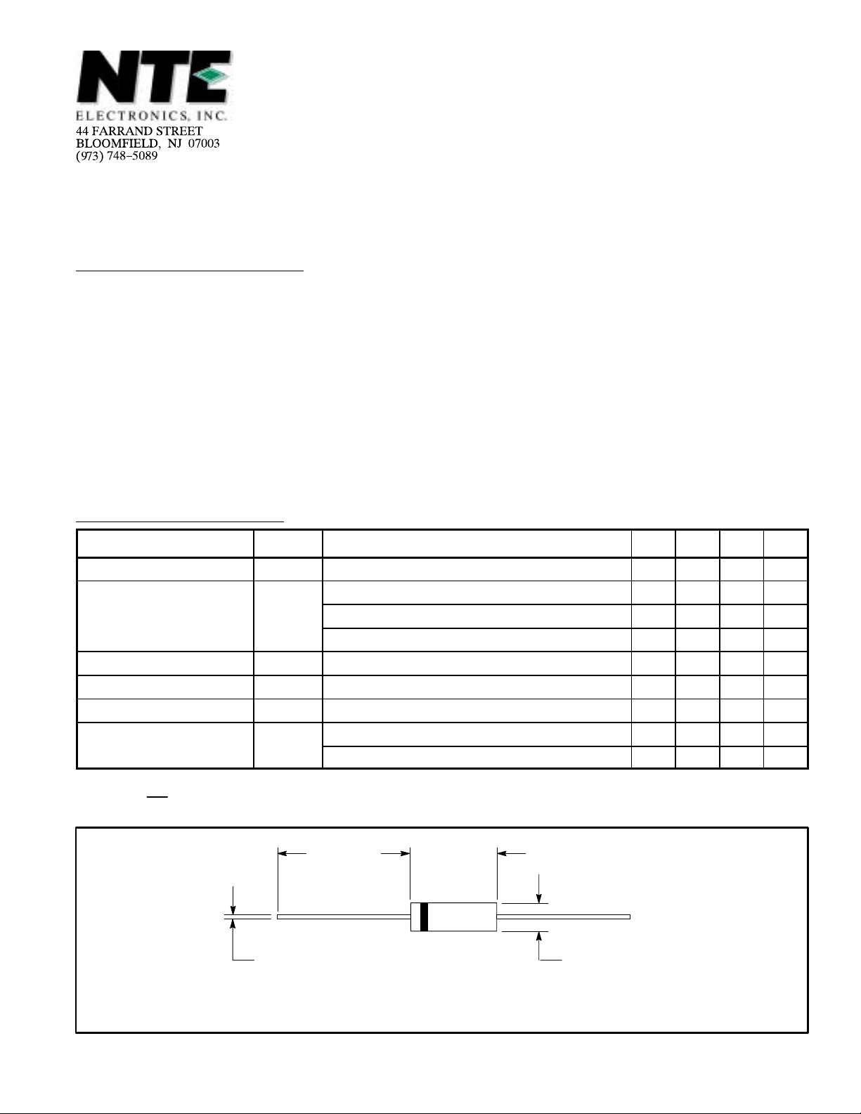
.022 (.509) Dia Max
IF = 10mA – – 1 V
F
VR = 20V – – 25 nA
R
VR = 20V, TJ = +150°C – – 50 µA
VR = 75V – – 5 µA
(BR)IR
VR = 0, f = 1MHz, VHF = 50mV – – 4 pF
D
VHF = 2V, f = 100MHz 45 – – %
r
IF = IR = 10mA, iR = 1mA – – 8 ns
rr
IF = 10mA, VR = 6V, iR = 0.1 IR, RL = 100Ω – – 4 nS
1.000
(25.4)
= 100µA, Note 1 100 – – V
.200
(5.08)
Min
Max
.090 (2.28)
Dia Max
Color Band Denotes Cathode
 Loading...