

NTE NTE4900 Datasheet
NTE4900
Surge Clamping, Overvoltage Transient Suppressor,
Unidirectional
Description:
The NTE4900 is a zener overvoltage transient suppressor in an axial lead type package designed
to protect voltage sensitive components from high voltage, high energy transients. This device has
excellent clamping capability, high surge capability, low zener impedance, and fast response time
making the NTE4900 ideal for use in communication systems, numerical controls, process controls,
medical equipment, business machines, power supplies and many other industrial/consumer applications, to protect CMOS, MOS and Bipolar integrated circuits.
Features:
D Peak Power: 1500W @ 1.0ms
D Maximum Clamp Voltage @ Peak Pulse Current
D Low Leakage: < 5.0µA Above 10V
Absolute Maximum Ratings:
Peak Power Dissipation (Non–Repetitive Current Pulse, TL ≤ +25°C), P
Steady State Power Dissipation (T
Derate Above T
Forward Curent Current (T
= +75°C 50mW/°C. . . . . . . . . . . . . . . . . . . . . . . . . . . . . . . . . . . . . . . . . . . . . . . .
L
= +25°C, Note 1), I
A
Operating Junction Temperature Range, T
Storage Temperature Range, T
Lead Temperature (During Soldering, 1/16” from case, 10sec), T
≤ +75°C, Lead length = 3/8”), P
L
FSM
J
stg
L
PK
D
–65° to +175°C. . . . . . . . . . . . . . . . . . . . . . . . . . . . . . . . . .
–65° to +175°C. . . . . . . . . . . . . . . . . . . . . . . . . . . . . . . . . . . . . . . . . .
Note 1. 1/2 Square W ave (or equivalent), PW = 8.3ms, Duty Cycle = 4 Pulses per minute maximum.
1500W. . . . . . . . . . . . . .
5W. . . . . . . . . . . . . . . . . . . . .
200A. . . . . . . . . . . . . . . . . . . . . . . . . . . . . . . . . . . .
+230°C. . . . . . . . . . . . . . . . . . . . .
Electrical Characteristics:
(TA = +25°C, VF = 3.5V Max, IF(Note 1) = 100A unless otherwise
specified)
Parameter Symbol Test Conditions Min Typ Max Unit
Breakdown Voltage V
Reverse Stand–Off Voltage V
Reverse Leakage Current I
Reverse Voltage (Clamping Voltage V
Clamping Voltage V
RWM
RSMIRSM
IT = 1mA 6 – – V
BR
Note 2 – – 5 V
V
R
C
= 5V – – 300 µA
RWM
= 120A – – 8.5 V
IPP = 30A – – 7.6 V
IPP = 60A – – 8.0 V
Note 1. 1/2 Square W ave (or equivalent), PW = 8.3ms, Duty Cycle = 4 Pulses per minute maximum.
Note 2. A Transient Suppressor is normally selected according to the maximum reverse stand–off
voltage (V
), which should be equal to or greater than the DC or continuous peak operat-
RWM
ing voltage level.
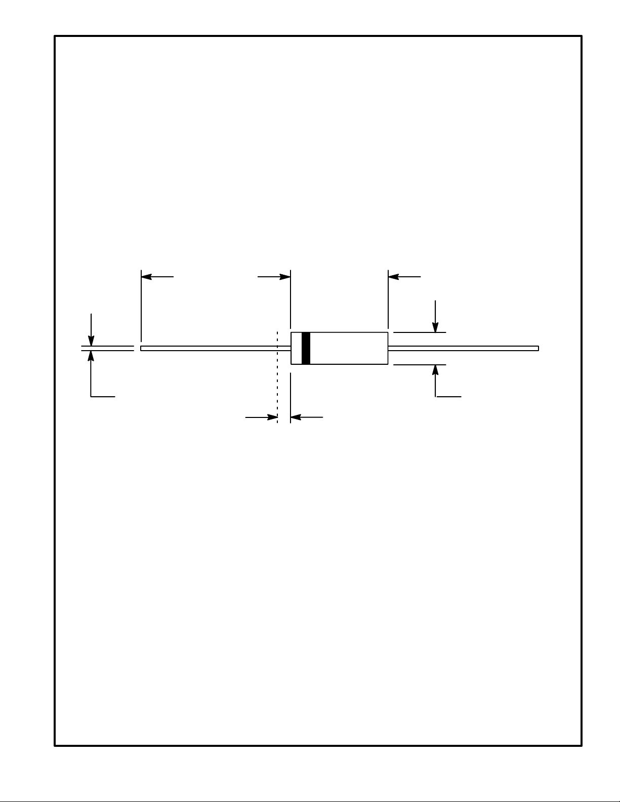
1.100 (27.94)
Min
.375 (9.52)
Max
.042 (1.07) Dia Max
(Unidirectional ONLY. Bidirectional devices
.050 (1.27) Max
(Both Ends)
Color Band Denotes Cathode
have NO band.)
.205 (5.21)
Dia Max
 Loading...