

NTE NTE4848, NTE4840, NTE4828, NTE4868, NTE4858 Datasheet
...
NTE4828 thru NTE4868
Surge Clamping, Transient Overvoltage Suppressor
Unidirectional
Description:
The NTE4800 Series of high power transient suppressors are Silicon PN Junction devices designed
for absorbtion of high voltage transients associated with power disturbances, switching and induced
lighting effects. These devices were designed to be used on the output of switching power supplies
and may be used to replace crowbar circuits.
They are able to withstand high levels of peak current while allowing a circuit breaker to trip of a fuse
to blow before shorting. This will enable the user to reset the breaker or replace the fuse and continue
operation. For this type of operation, it is recommended that a sufficient mounting surface be used
for dissipating the heat generated by the device during the transient or overvoltage condition.
Features:
D Glass Passivated Junction
D 5000W Peak Pulse Power Capability on 10/1000µs Waveform
D Repetition Rate (Duty Cycle): 0.05%
D Low Incremental Surge Resistance
D Fast Response Time
Absolute Maximum Ratings:
(TA = +25°C unless otherwise specified)
Minimum Peak Puse Power Dissipation (10/1000µs Waveform, Note 1), P
PPM
5000W. . . . . . . . . .
Peak Pulse Current (10/1000µs Waveform, Note 1), I
PPM
See Table. . . . . . . . . . . . . . . . . . . . . . . . . .
Steady State Power Dissipation (T
L
= +75°C, Lead Length .375” (9.5mm), Note 2), P
M(AV)
8W. . .
Peak Forward Surge Current, I
FSM
(8.3ms Single Half Sine–Wave Superimposed on Rated Load, Note 3) 400A. . . . . . . . . . . . .
Instantaneous Forward Voltage (I
F
= 100A, Note 3), V
F
3.5V. . . . . . . . . . . . . . . . . . . . . . . . . . . . . . . .
Operating Junction Temperature Range, T
J
–55° to +175°C. . . . . . . . . . . . . . . . . . . . . . . . . . . . . . . . . .
Storage Temperature Range, T
stg
–55° to +175°C. . . . . . . . . . . . . . . . . . . . . . . . . . . . . . . . . . . . . . . . . .
Lead Temperature (During Soldering, .375” (9.5mm) Lead Length, 10sec ), T
L
+300°C. . . . . . . . . .
Note 1. Non–repetitive current pulse, dereated above T
A
= +°C.
Note 2. Mounted on Copper Leaf area of 0.79in
2
(20mm2).
Note 3. Measured on 8.3ms single half sine–wave or equivalent square wave, duty cycle = 4 pulses
per minute maximum.
Electrical Characteristics: (TA = +25°C unless otherwise specified)
Maximum Ratings
NTE Type
Number
Maximum Reverse
Stand Off Voltage
(Volts)
Breakdown Voltage @ IT (Note 4)
(Volts)
Clamping Voltage
@ I
pp
(1msec)
(Volts)
Reverse Leakage
Current @ V
R
(µA)
Peak Pulse
Current
(Amps)
Temperature
Coefficient
of BV%/°C
V
R
V
BR
V
C
I
R
I
pp
Min Typ Max IT mA
4828 15.0 16.7 – 20.4 5.0 24.4 10.0 206.00 0.094
4840 24.0 26.7 – 29.5 5.0 38.9 10.0 128.00 0.101
4846 30.0 33.3 – 36.8 5.0 48.4 10.0 103.00 0.103
4848 33.0 36.7 – 40.6 5.0 53.3 10.0 94.00 0.104
4850 36.0 40.0 – 44.2 5.0 58.1 10.0 85.00 0.104
4858 48.0 53.3 – 58.9 5.0 77.4 10.0 65.00 0.106
4868 64.0 71.1 – 78.6 5.0 103.0 10.0 49.00 0.108
Note 4. V
(BR)
measured after IT applied for 300ms. IT = Square Wave Pulse or equivalent..
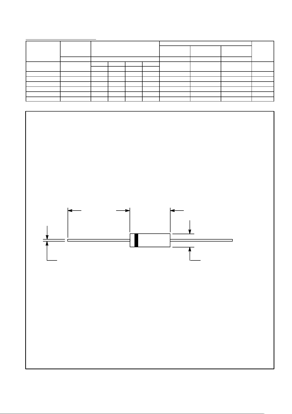
Color Band Denotes Cathode
1.000 (25.4)
Min
.360 (9.1)
Max
.360 (9.1) Dia Max
.052 (1.3) Dia Max
 Loading...