

NTE NTE3184, NTE3183 Datasheet
NTE3183 & NTE3184
Discrete Blue LED Indicators
Description:
The NTE3183 and NTE3184 are blue source color light emitting diodes made with GaN on SIC. It is
recommended that a wrist strap or anit–electrostatic glove be used when handling these devices as
static electricity and surge will damage these devices. All devices, equipment, and machinery must
be electrically grounded.
Features:
D Low Power Consumption
D Solid State Blue Light Source
NTE3183 (Blue Diffused)
NTE3184 (Clear Blue)
D Suitable for use in Full Color LED Displays and Indicators in Diagnostic/Analytical Equipment
Absolute Maximum Ratings: (TA = +25°C unless otherwise specified)
Reverse Voltage, V
DC Forward Current, I
Peak Forward Current (1/10 Duty Cycle, 0.1ms Pulse Width), I
Power Dissipation, P
Operating Temperature Range, T
Storage Temperature Range, T
R
F
F
D
opr
stg
Lead Temperature (During Soldering, .157 (4mm) below package base, 5sec max), T
–40° to +85°C. . . . . . . . . . . . . . . . . . . . . . . . . . . . . . . . . . . . . . . . .
–40° to +85°C. . . . . . . . . . . . . . . . . . . . . . . . . . . . . . . . . . . . . . . . . . .
L
5V. . . . . . . . . . . . . . . . . . . . . . . . . . . . . . . . . . . . . . . . . . . . . . . . . . . . . . . . . . . . . . . . .
30mA. . . . . . . . . . . . . . . . . . . . . . . . . . . . . . . . . . . . . . . . . . . . . . . . . . . . . . . . . . .
200mA. . . . . . . . . . . . . . . . . . . . . . .
105mW. . . . . . . . . . . . . . . . . . . . . . . . . . . . . . . . . . . . . . . . . . . . . . . . . . . . . . . . . . .
+260°C. . .
Electro–Optical Characteristics: (TA = +25°C unless otherwise specified)
Parameter Symbol Test Conditions Min Typ Max Unit
Forward Voltage V
Reverse Current I
Luminous Intensity
NTE3183
NTE3184 20 – 90 mcd
Viewing Angle
NTE3183
NTE3184 – 20 – deg.
I
2q1/
IF = 20mA – 4.5 5.5 V
F
VR = 5V – 10 – µA
R
IF = 20mA 12.5 – 40 mcd
V
Note 1 – 60 – deg.
2
Note 1. Viewing Angle is the off–axis angle at which the luminous intensity is half the axial luminous
intensity.
Electro–Optical Characteristics (Cont’d): (TA = +25°C unless otherwise specified)
Parameter Symbol Test Conditions Min Typ Max Unit
Peak Emission Wave Length λ
Spectral Line Half Width ∆λ IF = 20mA – 65 – nm
Capacitance C VF = 0, f = 1MHz – 100 – pF
PEAKIF
= 20mA – 430 – nm
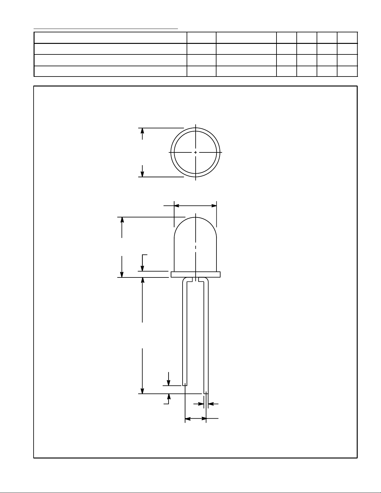
.126
(3.2)
Dia
.114 (2.9) Dia
.181
(4.6)
.040
(1.01)
1.063
(27.0)
Min
.060 (1.5) Typ
Cathode
.025 (0.63) Max Sq
.100 (2.54)
 Loading...