

NTE NTE3117, NTE3115, NTE3116 Datasheet
NTE3115, NTE3116, NTE3117
Bar Graph Display
Description:
The NTE3115 (High–Efficiency Red), NTE3116 (High Efficiency Green), and NTE3117 (Yellow) are
10–segment bar graph displays with separate anodes and cathodes for each light segment. The
packages are end stackable.
Features:
D Large Segments, Closely Spaced
D End Stackable
D Fast Switching, Excellent for Multiplexing
D Low Power Consumption
Absolute Maximum Ratings:
Power Dissipation (TA = +25°C) 750mW. . . . . . . . . . . . . . . . . . . . . . . . . . . . . . . . . . . . . . . . . . . . . . . . . . .
Derate Linearly from 50°C –14.3mW/°C. . . . . . . . . . . . . . . . . . . . . . . . . . . . . . . . . . . . . . . . . . . . .
Operating Temperature Range –40° to +85°C. . . . . . . . . . . . . . . . . . . . . . . . . . . . . . . . . . . . . . . . . . . . . .
Storage Temperature Range –40° to +85°C. . . . . . . . . . . . . . . . . . . . . . . . . . . . . . . . . . . . . . . . . . . . . . . .
Continuous Forward Current
Total
NTE3115, NTE3116 300mA. . . . . . . . . . . . . . . . . . . . . . . . . . . . . . . . . . . . . . . . . . . . . . . . . . . .
NTE3117 200mA. . . . . . . . . . . . . . . . . . . . . . . . . . . . . . . . . . . . . . . . . . . . . . . . . . . . . . . . . . . . . .
Per Segment
NTE3115, NTE3116 30mA. . . . . . . . . . . . . . . . . . . . . . . . . . . . . . . . . . . . . . . . . . . . . . . . . . . . .
NTE3117 25mA. . . . . . . . . . . . . . . . . . . . . . . . . . . . . . . . . . . . . . . . . . . . . . . . . . . . . . . . . . . . . . .
Reverse Voltage, Per Segment 6V. . . . . . . . . . . . . . . . . . . . . . . . . . . . . . . . . . . . . . . . . . . . . . . . . . . . . . .
Lead Temperature (During Soldering, 5sec max, Note 2) +260°C. . . . . . . . . . . . . . . . . . . . . . . . . . . . .
D Directly Compatible with IC’s
D Wide Viewing Angle
D Standard .300” DIP Lead Spacing
D Categorized for Luminous Intensity (Note 1)
Typical Thermal Characteristics:
Thermal Resistance, Junction–to–Free–Air, R
Wavelength Temperature Coefficient (Case Temperature) 1.0Å/°C. . . . . . . . . . . . . . . . . . . . . . . . . . . .
Forward Voltage Temperature Coefficient
NTE3115 –2.0mV/°C. . . . . . . . . . . . . . . . . . . . . . . . . . . . . . . . . . . . . . . . . . . . . . . . . . . . . . . . . . . . . .
NTE3116 1.4mV/°C. . . . . . . . . . . . . . . . . . . . . . . . . . . . . . . . . . . . . . . . . . . . . . . . . . . . . . . . . . . . . . .
NTE3117 –1.5mV/°C. . . . . . . . . . . . . . . . . . . . . . . . . . . . . . . . . . . . . . . . . . . . . . . . . . . . . . . . . . . . . .
Note 1. The average Luminous Intensity is obtained by summing the Luminous Intensity of each seg-
ment and dividing by the total number of segments. The standard of measurement is the
Photo Research Corp. “Spectra” Microcandela Meter (Model IV–D) corrected for wavelength. Intensity will not vary more than ±33.3% between all segments within a unit.
Note 2. Leads immersed to 1/16” (1.6mm) from the body of the device. Maximum unit surface tem-
perature is +140°C. For flux removal, Freon T F, Freon TE, isoproponal or water may be used
up to their boiling points.
thJA
160°C/W. . . . . . . . . . . . . . . . . . . . . . . . . . . . . . . . .
Electro–Optical Characteristics: (TA = +25°C unless otherwise specified)
Parameter Test Conditions Min Typ Max Unit
Forward Voltage
NTE3115, NTE3117
IF = 10mA – 2.0 2.5 V
NTE3116 – 2.2 3.0 V
Luminous Intensity (Unit Average) IF = 10mA, Note 1 510 – – µcd
Pulsed Luminous Intensity (NTE3116 Only) IF = 60mA peak, 1:6 DF 710 – – µcd
Peak Emission Wavelength
NTE3115 – 630 – nm
NTE3116 – 562 – nm
NTE3117 – 585 – nm
Spectral Line Half Width
NTE3115, NTE3117 – 40 – nm
NTE3116 – 30 – nm
Dynamic Resistance, Segment
NTE3115, NTE3117
IF = 20mA
– 26 – Ω
NTE3116 – 12 – Ω
Capacitance
NTE3115, NTE3117
V = 0, f = 1MHz
– 35 – pF
NTE3116 – 40 – pF
Switching Time IF = 10mA – 500 – ns
Reverse Voltage IR = 100µA 6.0 – – V
Note 1. The average Luminous Intensity is obtained by summing the Luminous Intensity of each seg-
ment and dividing by the total number of segments. The standard of measurement is the
Photo Research Corp. “Spectra” Microcandela Meter (Model IV–D) corrected for wavelength. Intensity will not vary more than ±33.3% between all segments within a unit.
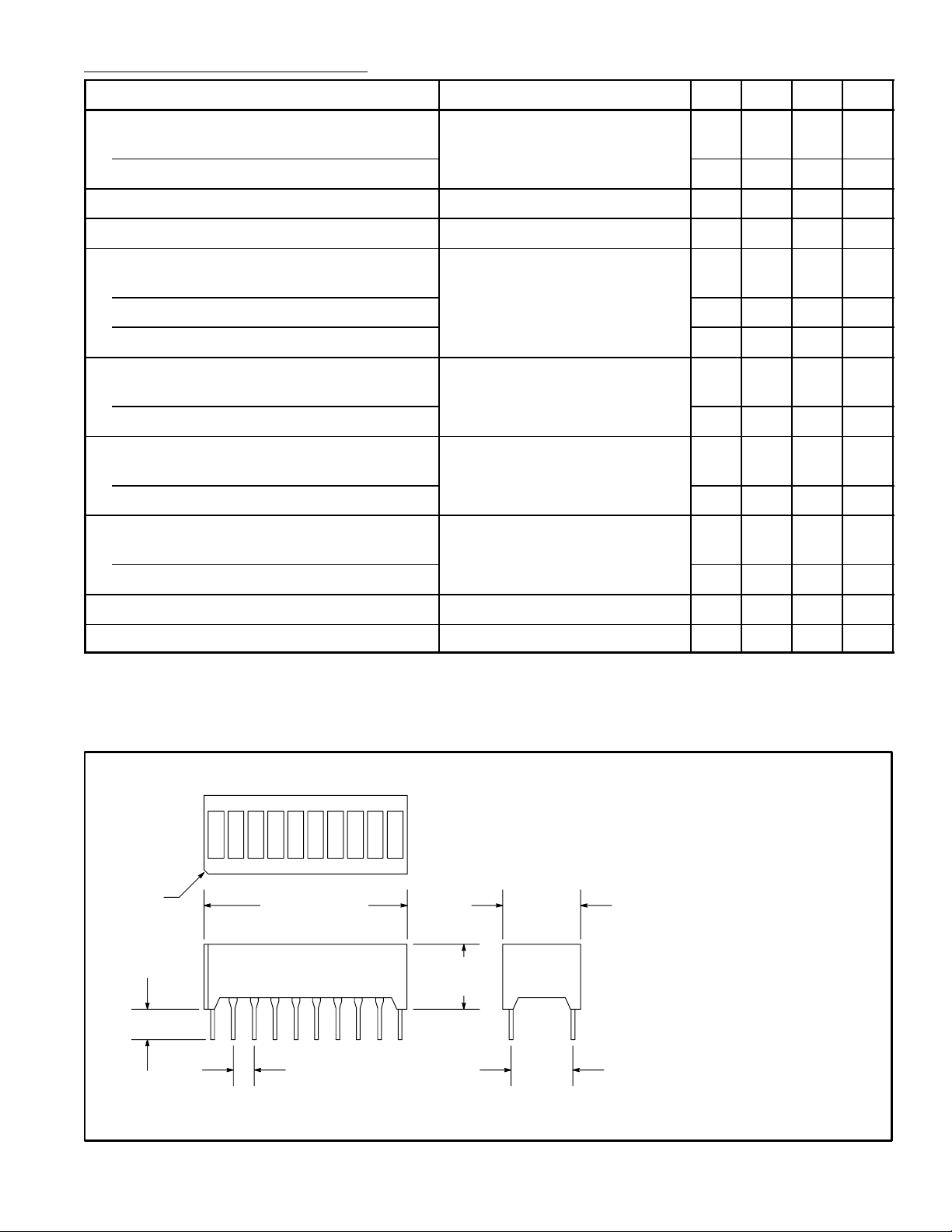
No. 1 Pin
Index
.150
(3.81)
1.000 (25.4) .380
(9.65)
.320
(8.12)
.100 (2.54)
.300
(7.62)
Pin Output Pin Output
1 D1 Anode 11 D10 Cathode
2 D2 Anode 12 D9 Cathode
3 D3 Anode 13 D8 Cathode
4 D4 Anode 14 D7 Cathode
5 D5 Anode 15 D6 Cathode
6 D6 Anode 16 D5 Cathode
7 D7 Anode 17 D4 Cathode
8 D8 Anode 18 D3 Cathode
9 D9 Anode 19 D2 Cathode
10 D10 Anode 20 D1 Cathode
 Loading...