

NTE NTE3104 Datasheet

NTE3104
Opto Interrupter Module
Photo Reflector, NPN Transistor Output
Description:
The NTE3104 is a subminiature photo reflector whose GaAs infrared emitting diode and silicon transistor are assembled in the same package allowing for easy installation and handling.
The NTE3104 has an excellent S/N ratio (more than 40dB) and contains a built–in filter for cutting
visible light.
Typical applications for the NTE3104 include strobe detection in audio turntables, tape end detection,
automatic vending machines, and various other automatic control units.
Absolute Maximum Ratings: (TA = +25°C unless otherwise specified)
Emitter
Forward Current, I
Continuous 50mA. . . . . . . . . . . . . . . . . . . . . . . . . . . . . . . . . . . . . . . . . . . . . . . . . . . . . . . . . . . . . . . .
Pulse (Note 1) 500mA. . . . . . . . . . . . . . . . . . . . . . . . . . . . . . . . . . . . . . . . . . . . . . . . . . . . . . . . . . . .
Continuous Reverse Voltage, V
Power Dissipation, P
Detector
Collector–Emitter Voltage, V
Emitter–Collector Voltage, V
Collector Current, I
Collector Power Dissipation, P
Coupled
Total Power Dissipation, P
Isolation Voltage (Note 2), V
Operating Temperature Range, T
Storage Temperature Range, T
F
R
D
CEO
ECO
C
C
tot
iso
opr
stg
–20° to +90°C. . . . . . . . . . . . . . . . . . . . . . . . . . . . . . . . . . . . . .
–30° to +100°C. . . . . . . . . . . . . . . . . . . . . . . . . . . . . . . . . . . . . . .
6V. . . . . . . . . . . . . . . . . . . . . . . . . . . . . . . . . . . . . . . . . . . . . . . . . . .
75mW. . . . . . . . . . . . . . . . . . . . . . . . . . . . . . . . . . . . . . . . . . . . . . . . . . . . . . . . .
25V. . . . . . . . . . . . . . . . . . . . . . . . . . . . . . . . . . . . . . . . . . . . . . . . . . .
6V. . . . . . . . . . . . . . . . . . . . . . . . . . . . . . . . . . . . . . . . . . . . . . . . . . . .
20mA. . . . . . . . . . . . . . . . . . . . . . . . . . . . . . . . . . . . . . . . . . . . . . . . . . . . . . . . . . .
75mW. . . . . . . . . . . . . . . . . . . . . . . . . . . . . . . . . . . . . . . . . . . . . . . . .
100mW. . . . . . . . . . . . . . . . . . . . . . . . . . . . . . . . . . . . . . . . . . . . . . . . . . .
1000V. . . . . . . . . . . . . . . . . . . . . . . . . . . . . . . . . . . . . . . . . . . . . . . . . .
Note 1. Pulse Width ≤ 10µs, Duty Ratio: 0.01
Note 2. R.H. = 40% to 60% for one minute.
Electro–Optical Characteristics:
Parameter Symbol Test Conditions Min Typ Max Unit
Emitter
Forward Voltage V
Pulse Forward Voltage V
Reverse Current I
F
FP
R
Peak Wavelength λ IF = 50mA, TA = +25°C – 940 – nm
Spectral Half Bandwidth ∆λ IF = 50mA, TA = +25°C – 50 – nm
Capacitance C
t
Detector
Dark Current I
Collector–Emitter Voltage V
Emitter–Collector Voltage V
CEO
(BR)CEOiC
(BR)ECOiC
Coupled
Output Current I
Collector Dark Current I
Rise Time t
Fall Time t
Isolation Resistance R
O
CEOD
r
f
iso
IF = 4mA – 1.08 1.15 V
IFP = 500mA – 1.4 – V
VR = 6V – – 1 µA
VR = 0, f = 1MHz – 35 – pF
VCE = 2V – – 20 nA
= 100µA 25 – – V
= 100µA 6 – – V
IF = 4mA, VCE = 2V, d = 1mm 12 – 125 µA
IF = 4mA, VCE = 2V – – 50 nA
VCE = 2V, IF = 4mA,
RL = 1kΩ, d = 1mm
– 70 500 µs
– 50 500 µs
R.H. = 40% to 60%, 250V at E–D – 1000 – MΩ
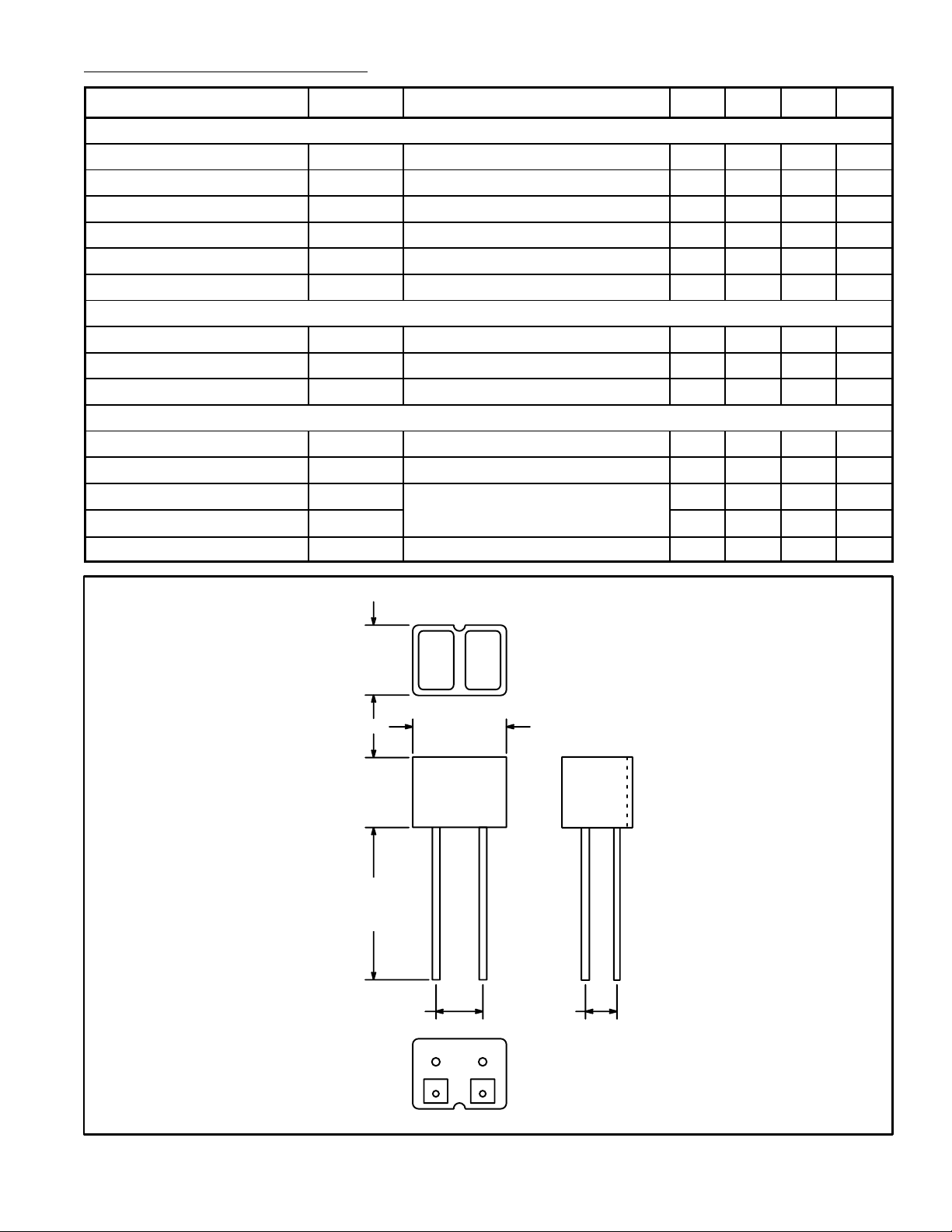
.126
(3.2)
.157 (4.0)
.118
(3.0)
.472
(12.0)
Min
.070 (1.8) .039 (1.0)
Cathode
Anode
Collector
Emitter
 Loading...