

NTE NTE3085 Datasheet

NTE3085
Optoisolator
Photon Coupled Bilateral Analog FET
Description:
The NTE3085 consists of a gallium arsenide infrared emitting diode coupled to a symmetrical silicon
photo detector. The detector is electrically isolated from the input and performs like an ideal isolated
FET designed for distortion–free control of low AC and DC analog signals.
Features:
As A Remote Variable Resistor
D ≤ 100Ω to ≥ 300MΩ
D ≥ 99.9% Linearity
D ≤ 15pF Shunt Capacitance
D ≥ 100GΩ I/O Isolation Resistance
As An Analog Signal Switch
D Extremely Low Offset Voltage
D 60V
Signal Capability
P–P
D No Charge Injection or Latchup
, t
D t
on
≤ 15µs
off
Absolute Maximum Ratings:
(TA = +25°C unless otherwise specified)
Infrared Emitting Diode
Power Dissipation (TA = +25°C), P
D
Derate Above 25°C 2.0mW/°C. . . . . . . . . . . . . . . . . . . . . . . . . . . . . . . . . . . . . . . . . . . . . . . . . . . . .
Forward Current, I
F
Continuous 60mA. . . . . . . . . . . . . . . . . . . . . . . . . . . . . . . . . . . . . . . . . . . . . . . . . . . . . . . . . . . . . . . .
Peak (Pulse Width 100µs, 100pps) 500mA. . . . . . . . . . . . . . . . . . . . . . . . . . . . . . . . . . . . . . . . . .
Peak (Pulse Width 1µs, 300pps) 3A. . . . . . . . . . . . . . . . . . . . . . . . . . . . . . . . . . . . . . . . . . . . . . . .
Reverse Voltage, V
R
Photo Detector
Power Dissipation (T
= +25°C), P
A
D
Derate Above 25°C 4.0mW/°C. . . . . . . . . . . . . . . . . . . . . . . . . . . . . . . . . . . . . . . . . . . . . . . . . . . . .
Breakdow Voltage, V
Continouos Detector Current, I
(BR)46
D
Total Device
Surge Isolation Voltage (Input to Output), V
ISO
Peak 2500V. . . . . . . . . . . . . . . . . . . . . . . . . . . . . . . . . . . . . . . . . . . . . . . . . . . . . . . . . . . . . . . . . . . . .
RMS 1770V. . . . . . . . . . . . . . . . . . . . . . . . . . . . . . . . . . . . . . . . . . . . . . . . . . . . . . . . . . . . . . . . . . . . . .
Steady–State Isolation Voltage (Input to Output), V
ISO
Peak 1500V. . . . . . . . . . . . . . . . . . . . . . . . . . . . . . . . . . . . . . . . . . . . . . . . . . . . . . . . . . . . . . . . . . . . .
RMS 1060V. . . . . . . . . . . . . . . . . . . . . . . . . . . . . . . . . . . . . . . . . . . . . . . . . . . . . . . . . . . . . . . . . . . . . .
Operating Temperature Range, T
Storage Temperature Range, T
opr
stg
Lead Temperature (During Soldering, 10sec Max), T
150mW. . . . . . . . . . . . . . . . . . . . . . . . . . . . . . . . . . . . . . . . . . . . . .
6V. . . . . . . . . . . . . . . . . . . . . . . . . . . . . . . . . . . . . . . . . . . . . . . . . . . . . . . . . . . . . . . . .
300mW. . . . . . . . . . . . . . . . . . . . . . . . . . . . . . . . . . . . . . . . . . . . . .
±30V. . . . . . . . . . . . . . . . . . . . . . . . . . . . . . . . . . . . . . . . . . . . . . . . . . . . . . . . .
±100mA. . . . . . . . . . . . . . . . . . . . . . . . . . . . . . . . . . . . . . . . . . . . . . . . . .
–55° to +100°C. . . . . . . . . . . . . . . . . . . . . . . . . . . . . . . . . . . . . . . .
–55° to +150°C. . . . . . . . . . . . . . . . . . . . . . . . . . . . . . . . . . . . . . . . . .
L
+260°C. . . . . . . . . . . . . . . . . . . . . . . . . . . . . . . .
Electrical Characteristics: (TA = +25°C unless otherwise specified)
Parameter Symbol Test Conditions Min Typ Max Unit
Infrared Emitting Diode
Forward Voltage V
Reverse Current I
IF = 16mA – 1.1 1.75 V
F
VR = 6V – – 10 µA
R
Capacitance V = 0, f = 1MHz – 50 – pF
Photo–Detector (Either Polarity)
Breakdown Voltage V
Off–State Dark Current I
(BR)46I46
46
= 10µA, IF = 0 30 – – V
V46 = 15V, IF = 0 – – 50 nA
V46 = 15V, IF = 0, TA = +100°C – – 50 µA
Off–State Resistance r
Capacitance C
46
V46 = 15V, IF = 0 300 – – MΩ
V46 = 0, IF = 0, f = 1MHz – – 15 pF
46
Coupled Electrical Characteristics
On–State Resistance r
46
IF = 16mA, I46 = 100µA – – 200 Ω
IF = 16mA, I64 = 100µA – – 200 Ω
Isolation Resistance (Input to Output) V
ISO
V10 = 500V 100 – – GΩ
Input to Output Capacitance V10 = 0, f = 1MHz – – 2.5 pF
Turn–On Time t
Turn–Off Time t
Resistance, Non–Linearity and
Asymmetry
on
off
IF = 16mA, RL = 50Ω, V46 = 5V – – 15 µs
– – 15 µs
IF = 16mA, i46 = 25µA
RMS
,
– – 0.1 %
f = 1kHz
.070 (1.78) Max
.200
(5.08)
Max
.085 (2.16) Max
546
123
.350 (8.89)
Max
.100 (2.54)
.260
(6.6)
Max
.350
(8.89)
Max
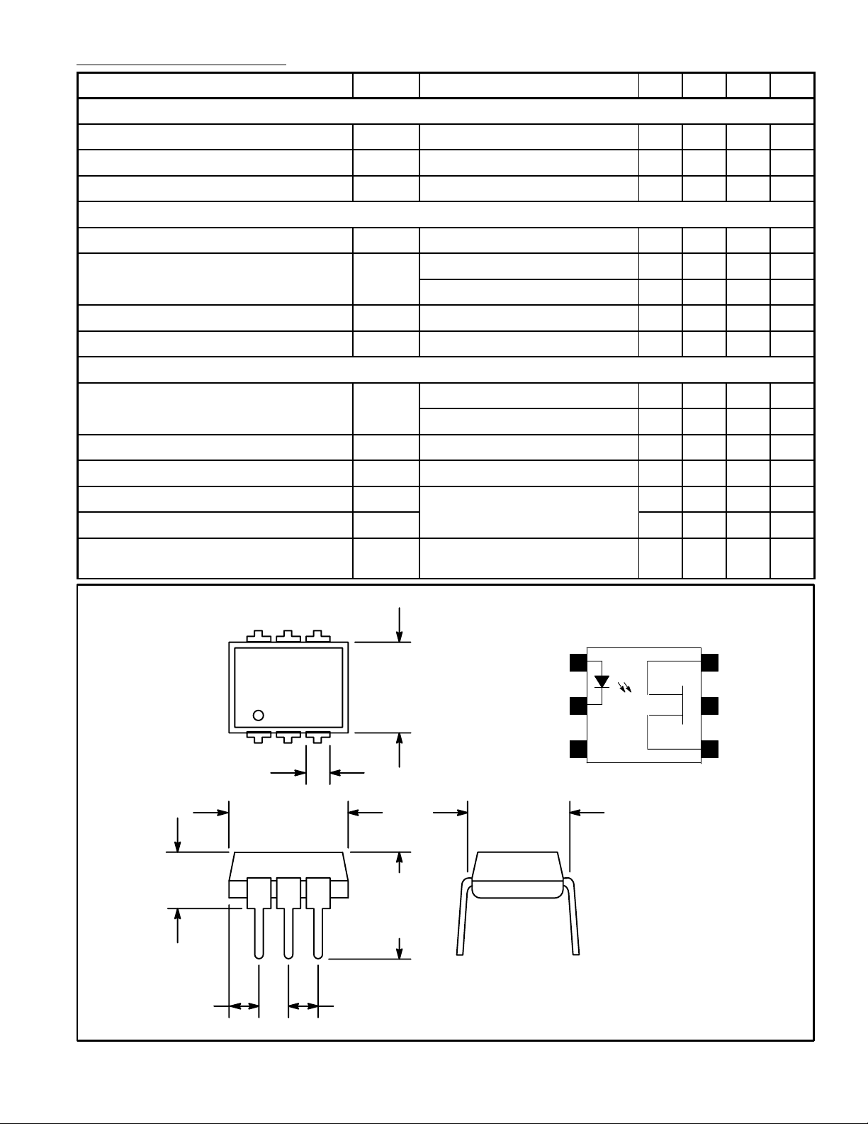
Anode
Cathode
.300 (7.62)
1
2
3N.C.
6
5
4
Drain
N.C.
Source
 Loading...