

NTE NTE3051 Datasheet

NTE3051
0.27” Polarity and Overflow
Numeric Display, Common Anode
Description:
The N TE3051 d isplay i s m ounted o n a lead–frame a ssembly w hich is t hen c ast w i thin a c lear , e lectrically
non–conductive, transparent plastic compound.
Features:
D 0.27” High Characters
D High Brightness
D Low Power Requirements
D Single–Plane Wide–Angle Visibility
D Compatible with Most TTL and DTL Circuits
Absolute Raximum Ratings:
Reverse Voltage (T
= +25°C), V
A
(Over Ambient Temperature Range unless otherwise specified)
R
Each Segment 6V. . . . . . . . . . . . . . . . . . . . . . . . . . . . . . . . . . . . . . . . . . . . . . . . . . . . . . . . . . . . . . . .
Decimal Point 3V. . . . . . . . . . . . . . . . . . . . . . . . . . . . . . . . . . . . . . . . . . . . . . . . . . . . . . . . . . . . . . . . .
Peak Forward Current, each Segment or Decimal Point (Note 1), I
Continuous Forward Current, I
F
FP
Each Segment or Decimal Point 30mA. . . . . . . . . . . . . . . . . . . . . . . . . . . . . . . . . . . . . . . . . . . . . .
Total Device 150mA. . . . . . . . . . . . . . . . . . . . . . . . . . . . . . . . . . . . . . . . . . . . . . . . . . . . . . . . . . . . . .
Operating Ambient Temperature Range, T
Storage Temperature Range, T
stg
A
–55° to +100°C. . . . . . . . . . . . . . . . . . . . . . . . . . . . . . . . . . . . . . . . . .
Note 1. This value applies for PRR ≥ 60Hz, Duty Cycle ≤ 10%.
Operating Characteristics:
Parameter Symbol Test Conditions Min Typ Max Unit
Luminous Intensity
Each Segment
Decimal Point 40 110 – µcd
Wavelength at Peak Emission
Each Segment
Decimal Point 645 665 685 nm
(TA = +25°C unless otherwise specified)
I
λ
IF = 20mA, Note 2 100 275 – µcd
V
IF = 20mA 640 660 680 nm
P
200mA. . . . . . . . . . . . . . . . . . .
0° to +70°C. . . . . . . . . . . . . . . . . . . . . . . . . . . . . . . . . . . . .
Spectral Bandwidth between Half Points B IF = 20mA – 20 – nm
Note 2. Luminous intensity is measured with a solar cell and filter combination which approximates
the CIE (International Commission on Illumination) eye–response curve.
Operating Characteristics (Cont’d): (TA = +25°C unless otherwise specified)
Parameter Symbol Test Conditions Min Typ Max Unit
Average Temperature Coefficient of Static Forward Voltage
Each Segment
Decimal Point – 1.4 – mV/°C
Static Reverse Current I
Anode–to–Cathode Capacitance
Each Segment
Decimal Point – 120 – pF
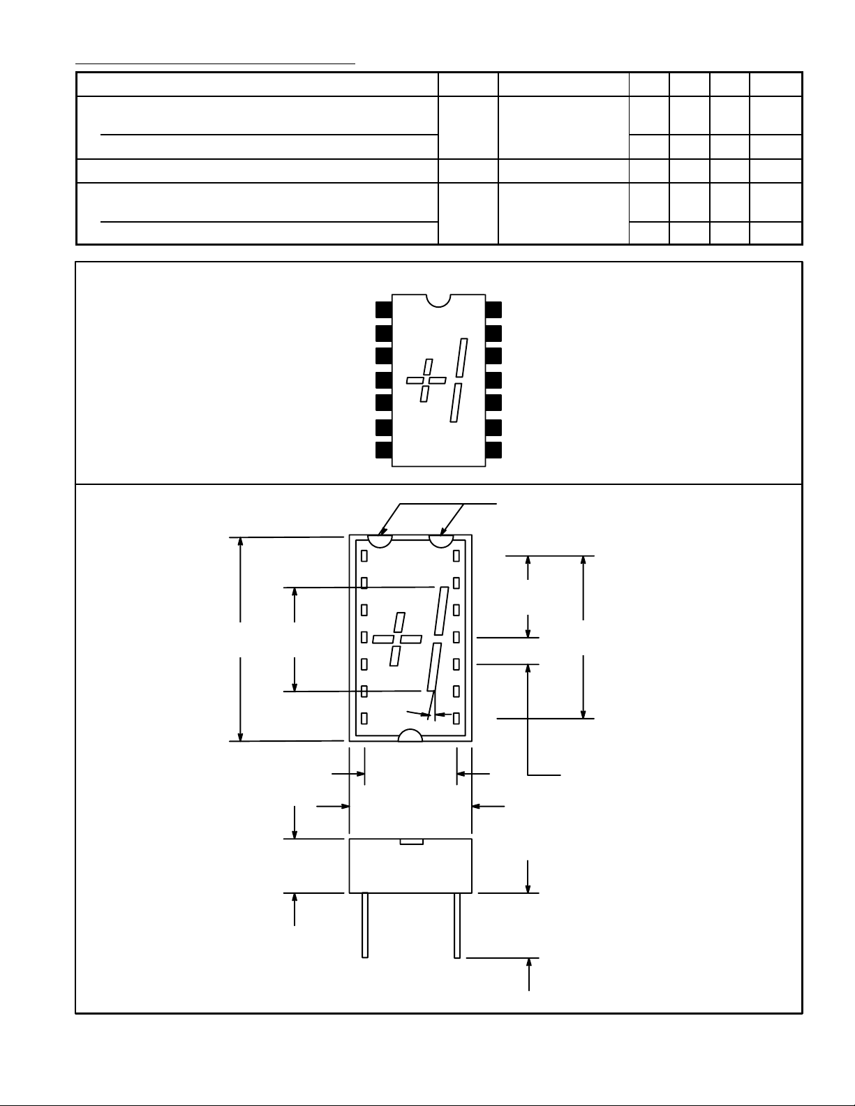
Pin Connection Diagram
Anode Common C/D
No Pin
No Pin
No Pin
1
2
3
C
4
5No Pin
D
6No Pin
7Cathode D
IF = 20mA,
= 0° to +70°C
T
A
VR = 3V – – 100 µA
R
C VR = 0, f = 1MHz – 85 – pF
Anode Common A/B
14
13
No Pin
No Pin
12
A
11
Cathode A
10 Cathode B
B
– –2.7 – mV/°C
9 No Pin
8 Cathode C
Orientation
Marks
.760
(19.3)
.270
(6.86)
.120
(3.05)
1
7
10°
.300 (7.62)
.400 (10.16)
14
.300
(7.62)
.600
(15.24)
8
.100 (2.54) Typ
.200
(5.08)
Min
 Loading...