

NTE NTE3050 Datasheet
NTE3050
Seven Segment LED Display
.270 Inch, Common Anode, LHDP
Features:
D .270” High Characters
D High Brightness
D Low Power Requirements
Absolute Maximum Ratings: (TA = 0° to +70°C unless othwerwise specified)
Reverse Voltage (TA = +25°C), V
R
Each Segment 6V. . . . . . . . . . . . . . . . . . . . . . . . . . . . . . . . . . . . . . . . . . . . . . . . . . . . . . . . . . . . . . . .
Decimal Point 3V. . . . . . . . . . . . . . . . . . . . . . . . . . . . . . . . . . . . . . . . . . . . . . . . . . . . . . . . . . . . . . . . .
Peak Forward Current (Each Segment or Decimal Point, Note 1), IFpeak 200mA. . . . . . . . . . . . . . .
Continuous Forward Current, I
F
Each Segment or Decimal Point 30mA. . . . . . . . . . . . . . . . . . . . . . . . . . . . . . . . . . . . . . . . . . . . . .
Total Device 240mA. . . . . . . . . . . . . . . . . . . . . . . . . . . . . . . . . . . . . . . . . . . . . . . . . . . . . . . . . . . . . .
Operating Ambient Temperature Range, T
Storage Temperature Range, T
stg
A
Note 1. This value applies for PRR ≥ 60Hz, Duty Cycle ≤ 10%.
D Left Hand Decimal Point (LHDP)
D Single–Plane Wide–Angle Visibility
D Compatible with Most TTL and DTL Circuits
0° to +70°C. . . . . . . . . . . . . . . . . . . . . . . . . . . . . . . . . . . . .
–55° to +100°C. . . . . . . . . . . . . . . . . . . . . . . . . . . . . . . . . . . . . . . . . .
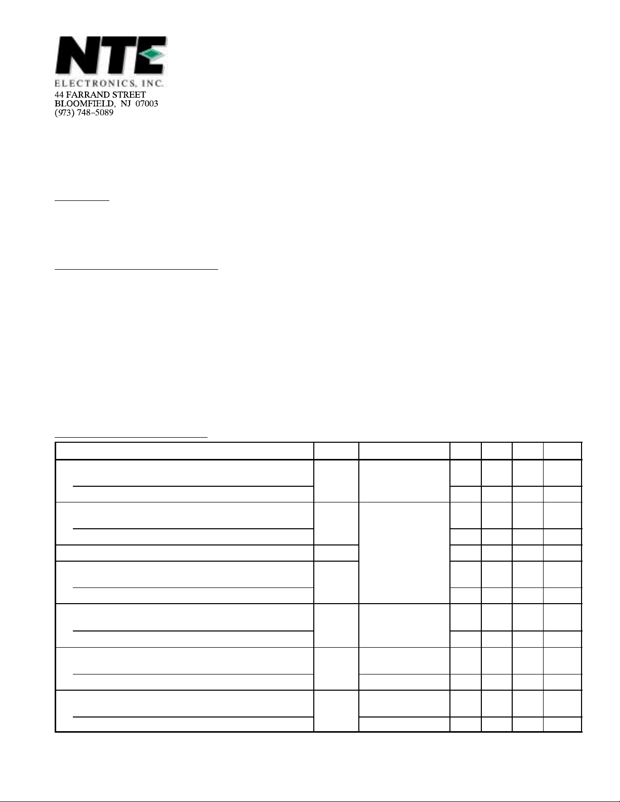
Operating Characteristics: (TA = +25°C unless otherwise specified)
Parameter Symbol Test Conditions Min Typ Max Unit
Luminous Intensity
Each Segment
Decimal Point 40 110 – µcd
Wavelength at Peak Emission
Each Segment
Decimal Point 645 665 685 nm
Spectral Bandwidth between Half–Power Points B – 20 – nm
Static Forward Voltage
Each Segment
Decimal Point 1.5 1.65 2.0 V
Average T emperature Coefficient of Static Forward Voltage
Each Segment
Decimal Point
Static Reverse Current
Each Segment
Decimal Point VR = 3V – – 100 µA
Anode–to–Cathode Capacitance
Each Segment
Decimal Point – 120 – pF
I
V
IF = 20mA, Note 2
λ
V
α
I
C
IF = 20mA
P
F
VF
IF = 20mA,
TA = 0° to +70°C
R
VR = 6V
VR = 0, f = 1MHz
100 275 – µcd
640 660 680 nm
3.0 3.4 3.8 V
– –2.7 – mV/°C
– –1.4 – mV/°C
– – 100 µA
– 85 – pF
Note 2. Luminous intensity is measured with a solar cell and filter combination which approximates
the CIE (International Commission on Illumination) eye–response curve.
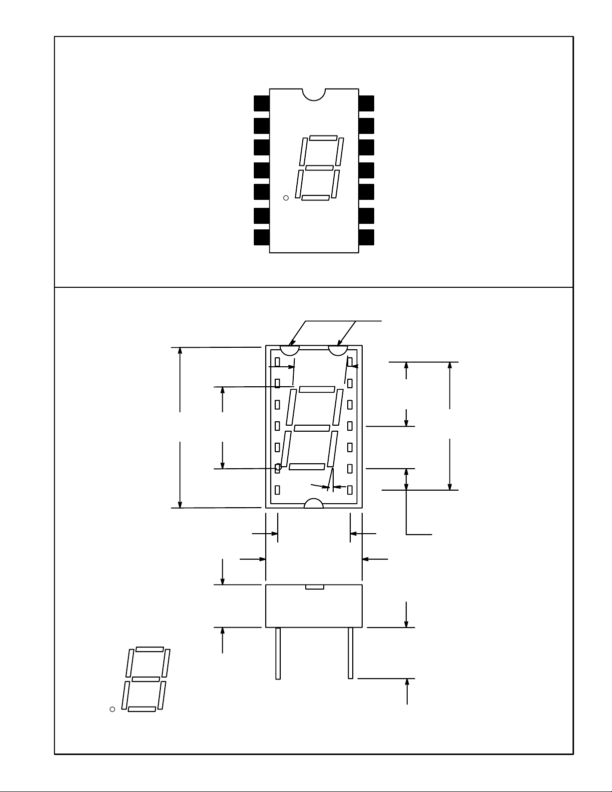
Pin Connection Diagram
Cathode A
Cathode F
Common Anode
No Pin
.760
(19.3)
.270
(6.86)
1
2
A
3
FBG
4
EC
5No Pin
6Cathode D.P.
DD.P.
7Cathode E
1
.187
(4.75)
14
Common Anode
13
Cathode B
12
No Pin
11
Cathode G
10 Cathode C
9 Common Anode
8 Cathode D
Orientation
Marks
14
.300
(7.62)
.600
(15.24)
.120
(3.05)
A
FBG
EC
DD.P.
78
10°
.300 (7.62)
.100 (2.54) Typ
.400 (10.16)
.200
(5.08)
Min
 Loading...