

NTE NTE3044 Datasheet

NTE3044
Optoisolator
NPN Darlington Transistor Output
Description:
The NTE3044 consists of a gallium arsenide infrared emitting diode optically coupled to a monolithic
silicon photodarlington detector in an 6–Lead DIP type package. This device is designed for use in
applications requiring high sensitivity at a low input current.
Features:
D High Sensitivity to Low Input Drive Current
D High Collector–Emitter Breakdown Voltage
D No Base Conncetion for Improved Noise Immunity
Applications:
D Appliances, Measuring Instruments
D I/O Interfaces for Computers
D Programmable Controllers
D Portable Electronics
D Interfacing and Coupling Systems of Different Potentials and Impedances
D Solid State Relays
Absolute Maximum Ratings:
(TA = +25°C unless otherwise specified)
Input LED
Reverse Voltage, V
Continuous Forward Current, I
R
F
LED Power Dissipation (with Negligible Power in Output Detector, T
= +25°C), P
A
D
3V. . . . . . . . . . . . . . . . . . . . . . . . . . . . . . . . . . . . . . . . . . . . . . . . . . . . . . . . . . . . . . . . .
60mA. . . . . . . . . . . . . . . . . . . . . . . . . . . . . . . . . . . . . . . . . . . . . . . . . . . .
120mW. . . . .
Derate Above 25°C 1.41mW/°C. . . . . . . . . . . . . . . . . . . . . . . . . . . . . . . . . . . . . . . . . . . . . . . . . . . .
Output Detector
Collector–Emitter Voltage, V
Emitter–Collector Voltage, V
CEO
ECO
Detector Power Dissipation (with Negligible Power in Output Detector, T
= +25°C), P
A
D
80V. . . . . . . . . . . . . . . . . . . . . . . . . . . . . . . . . . . . . . . . . . . . . . . . . . . . . .
5V. . . . . . . . . . . . . . . . . . . . . . . . . . . . . . . . . . . . . . . . . . . . . . . . . . . . . . .
150mW.
Derate Above 25°C 1.76mW/°C. . . . . . . . . . . . . . . . . . . . . . . . . . . . . . . . . . . . . . . . . . . . . . . . . . . .
Total Device
Isolation Surge Voltage (Peak AC Voltage, 60Hz, 1sec Duration, Note 1), V
Total Device Power Dissipation (T
= +25°C), P
A
D
ISO
7500V. . . . . . . . . . .
250mW. . . . . . . . . . . . . . . . . . . . . . . . . . . . . . . . . . .
Derate Above 25°C 2.94mW/°C. . . . . . . . . . . . . . . . . . . . . . . . . . . . . . . . . . . . . . . . . . . . . . . . . . . .
Ambient Operating Temperature Range, T
Storage Temperature Range, T
stg
A
Lead Temperature (During Soldering, 1/16” from Case, 10sec), T
L
–55° to +100°C. . . . . . . . . . . . . . . . . . . . . . . . . . . . . . . . . .
–55° to +150°C. . . . . . . . . . . . . . . . . . . . . . . . . . . . . . . . . . . . . . . . . .
+260°C. . . . . . . . . . . . . . . . . . . . .
Note 1. Isolation surge voltage is an internal dielectric breakdown rating. For this test, Pin1 and Pin2
are common, and Pin4, Pin5, and Pin6 are common.
Electrical Characteristics: (TA = +25°C unless otherwise specified)
Parameter Symbol Test Conditions Min Typ Max Unit
Input LED
Reverse Leakage Current I
Forward Voltage V
Capacitance C VR = 0, f = 1MHz – 18 – pF
Photodarlington (IF = 0)
Collector–Emitter Dark Current I
Collector–Emitter Breakdown Voltage V
Emitter–Collector Breakdown Voltage V
Coupled
Collector Output Current I
Isolation Surge Voltage V
Isolation Resistance R
Isolation Capacitance C
Switching
Turn–On Time t
Turn–Off Time t
Rise Time t
Fall Time t
R
CEO
(BR)CEOIC
(BR)ECOIE
C
ISO
ISO
ISO
on
off
VR = 3V – 0.05 10 µA
IF = 10mA – 1.15 2.0 V
F
VCE = 60V – – 1 µA
= 1mA 80 – – V
= 100µA 5 – – V
VCE = 1.5V, IF = 10mA 30 – – mA
60Hz Peak AC, 5sec, Note 2, Note 3 7500 – – V
V = 500V, Note 2 – 10
V = 0, f = 1MHz, Note 2 – 0.2 – pF
VCC = 10V, RL = 100Ω,
IF = 5mA
r
f
– 3.5 – µs
– 95 – µs
– 1 – µs
– 2 – µs
11
– Ω
Note 2. For this test , L E D Pin1 a n d Pin2 a r e commo n a n d P h ot ot ra ns is to r Pin4 a n d Pin5 are comm on .
Note 3. Isolation Surge Voltage, V
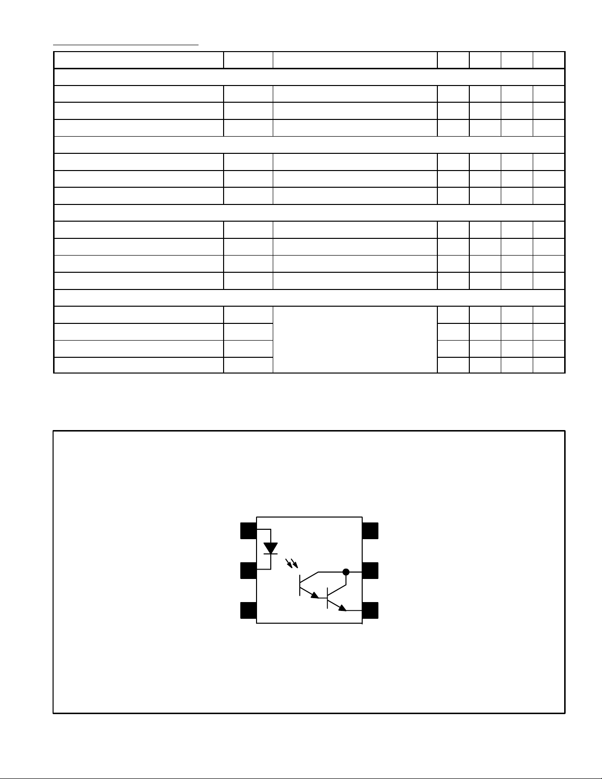
Anode
Cathode
, is an internal device dielectric breakdown rating.
ISO
Pin Connection Diagram
1
2
3N.C.
6
N.C.
5
Collector
Emitter
4
 Loading...