

NTE NTE3025 Datasheet
NTE3025
Light Emitting Diode (LED)
Description:
The NTE3025 is a red Light emitting Gallium Arsenide Phosphide diode in a T–1 3/4 (5mm) type package designed for use in applications such as instruments, printed circuit board indicators, and board
mounted panel displays.
Features:
D Low Power Consumption
D High Intensity
D IC Compatible/Low Current Requirements
D Versatile mounting on P.C. board or panel
D Reliable and Rugged
Absolute Maximum Ratings: (TA = +25°C unless otherwise specified)
Power Dissipation, P
Peak Forward Current (1/10 Duty Cycle, 0.1ms Pulse Width), I
Continuos Forward Current, I
D
F(Peak)
F
Derate Linearly Above 25°C 0.5mA/°C. . . . . . . . . . . . . . . . . . . . . . . . . . . . . . . . . . . . . . . . . . . . . .
Reverse Voltage, V
Operating Temperature Range, T
Storage Temperature Range, T
R
A
stg
Lead Temperature (During Soldering, .063 in. (1.6mm) from Body for 5sec), T
–55° to +100°C. . . . . . . . . . . . . . . . . . . . . . . . . . . . . . . . . . . . . . . . . .
–55° to +100°C. . . . . . . . . . . . . . . . . . . . . . . . . . . . . . . . . . . . . . . . . .
L
110mW. . . . . . . . . . . . . . . . . . . . . . . . . . . . . . . . . . . . . . . . . . . . . . . . . . . . . . . . . . .
200mA. . . . . . . . . . . . . . . . . .
40mA. . . . . . . . . . . . . . . . . . . . . . . . . . . . . . . . . . . . . . . . . . . . . . . . . . . . .
5V. . . . . . . . . . . . . . . . . . . . . . . . . . . . . . . . . . . . . . . . . . . . . . . . . . . . . . . . . . . . . . . . .
+260°C. . . . . . . . . .
Electrical/Optical Characteristics: (TA = +25°C unless otherwise specified)
Parameter Symbol Test Conditions Min Typ Max Unit
Luminous Intensity I
Viewing Angle 2Θ1/
Peak Emission Wavelength λP – 655 – nm
Spectral Line Half Width ∆λ – 40 – nm
Forward Voltage V
Reverse Current I
Capacitance C VF = 0, f = 1MHz – 30 – pF
V
F
R
IF = 10mA, Note 1 0.3 1.1 – mcd
Note 2 – 36 – deg.
2
IF = 20mA – 1.7 2.0 V
VR = 5V – – 100 µA
Note 1. Luminous intensity is measured with a light sensor and filter combination that approximates
the CIE (Commission Internationale De L′Eclairage) eye–response curve.
Note 2. Θ1/2 is the off–axis angle at which the liminous intensity is half the axial luminous intensity.
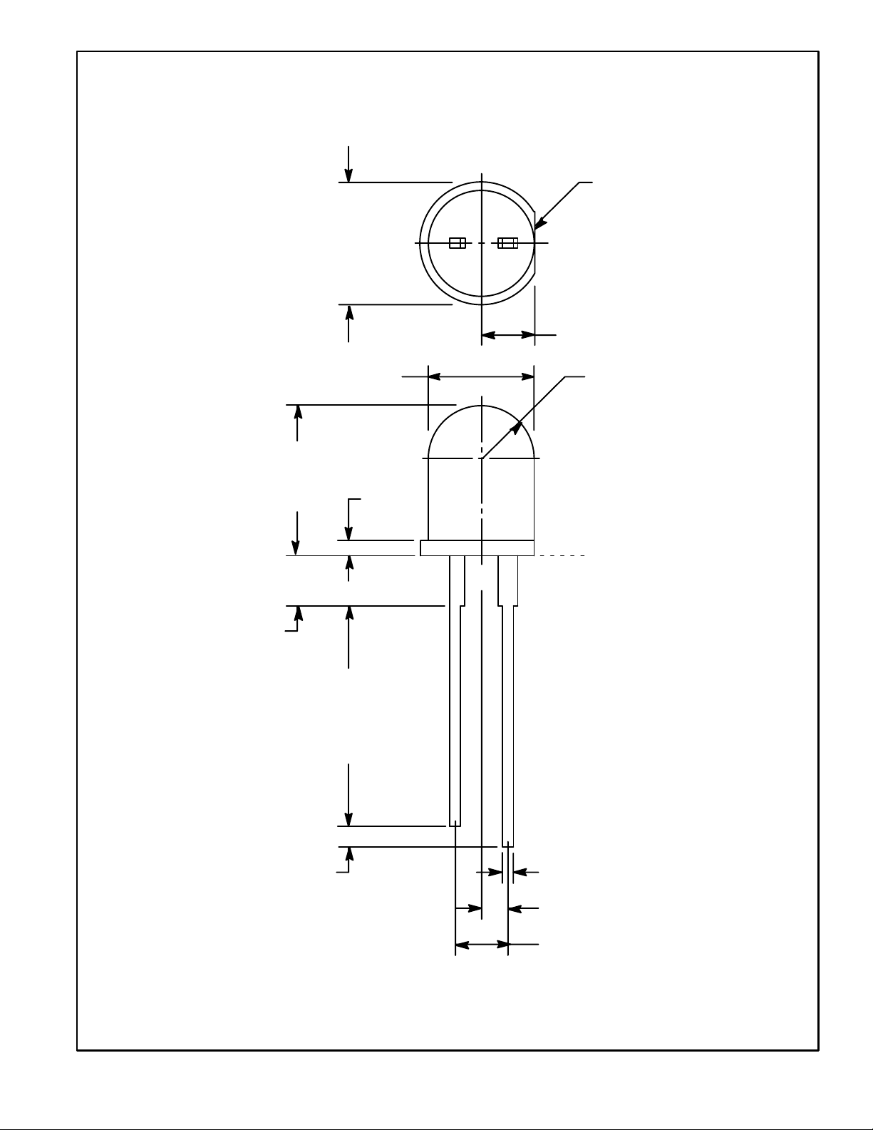
.230
(5.84)
Dia
Flat Denotes
Cathode
.100 (2.54)
.100 (2.54)
.200 (5.08) Dia
.340
(6.63)
.040
(1.01)
.750
(19.05)
Min
.100 (2.54) R
Seating Plane
.050 (1.27) Typ
.025 (0.63) Max Sq
.050 (1.27)
.100 (2.54)
Tolerance ±.010 (.254)
 Loading...