

NTE NTE3001 Datasheet

NTE3001
Light Emitting Diode
Miniature, Diffused Red
Description:
The NTE3001 is a diffused Gallium Arsenide Phosphide diode mounted in a two lead epoxy package
with a red diffused lens. On forward bias, this device emits a spectrally narrow band of visible light
which peaks at 660nm.
The NTE3001 is intended for high volume indicator light applications where low cost, high reliability ,
and top performance are required. Major usage is in applications such as diagnostic lights on printed
circuit boards and panel lights. This device can be used to displace subminiature lamps as small as
T3/4 size.
Features:
D Low Cost
D Bright
D Compatible with Integrated Circuits
D Long Life, Rugged
D Small Size: T–3/4
D Easily Assembled in Arrays
Absolute Maximum Ratings:
Power Dissipation (TA = +25°C) 80mW. . . . . . . . . . . . . . . . . . . . . . . . . . . . . . . . . . . . . . . . . . . . . . . . . . . .
Derate linearly from 25°C 1.6mW/°C. . . . . . . . . . . . . . . . . . . . . . . . . . . . . . . . . . . . . . . . . . . . . . .
Forward Current
Continuous 40mA. . . . . . . . . . . . . . . . . . . . . . . . . . . . . . . . . . . . . . . . . . . . . . . . . . . . . . . . . . . . . . . .
Peak (1µsec pulse width, 0.3% duty cycle) 1.0A. . . . . . . . . . . . . . . . . . . . . . . . . . . . . . . . . . . . .
Reverse Voltage 5.0V. . . . . . . . . . . . . . . . . . . . . . . . . . . . . . . . . . . . . . . . . . . . . . . . . . . . . . . . . . . . . . . . . .
Operating Temperature Range –55° to 100°C. . . . . . . . . . . . . . . . . . . . . . . . . . . . . . . . . . . . . . . . . . . . . .
Storage Temperature Range –55° to 100°C. . . . . . . . . . . . . . . . . . . . . . . . . . . . . . . . . . . . . . . . . . . . . . . .
Lead Temperature (During Soldering, 5sec max, Note 1) +230°C. . . . . . . . . . . . . . . . . . . . . . . . . . . . .
Typical Thermal Characteristics:
Wavelength Temperature Coefficient (Case Temperature) 0.3nm/°C. . . . . . . . . . . . . . . . . . . . . . . . . .
Forward Voltage Temperature Coefficient –2.0mV/°C. . . . . . . . . . . . . . . . . . . . . . . . . . . . . . . . . . . . . . .
Note 1. The leads of the device were immersed in molten solder at +230°C to a point 1/16 inch from
the body of the device with a dwell time of 5 seconds.
Electro–Optical Characteristics
Parameter Test Conditions Min Typ Max Unit
Luminous Intensity IF = 20mA, Note 2, Note 4 0.4 1.0 – mcd
Peak Emission Wavelength IF = 20mA – 660 – nm
Spectral Line Halfwidth IF = 20mA – 20 – nm
Forward Voltage IF = 20mA – 1.65 2.0 V
Capacitance V = 0 – 80 – pF
Rise and Fall Time 50Ω system, IF = 20mA – 50 – ns
Reverse Current VR = 3.0V – 5.0 – nA
View Angle Between 50% points – 80 – degrees
Note 2. As measured with a Photo Research Corp. “SPECTRA” Microcandela Meter (Model IV–D)
Note 3. The axis of spatial distribution are typically within a 10° cone with reference to the central
axis of the device.
Note 4. Luminous intensity guaranteed to a 2.5% AQL inspection plan.
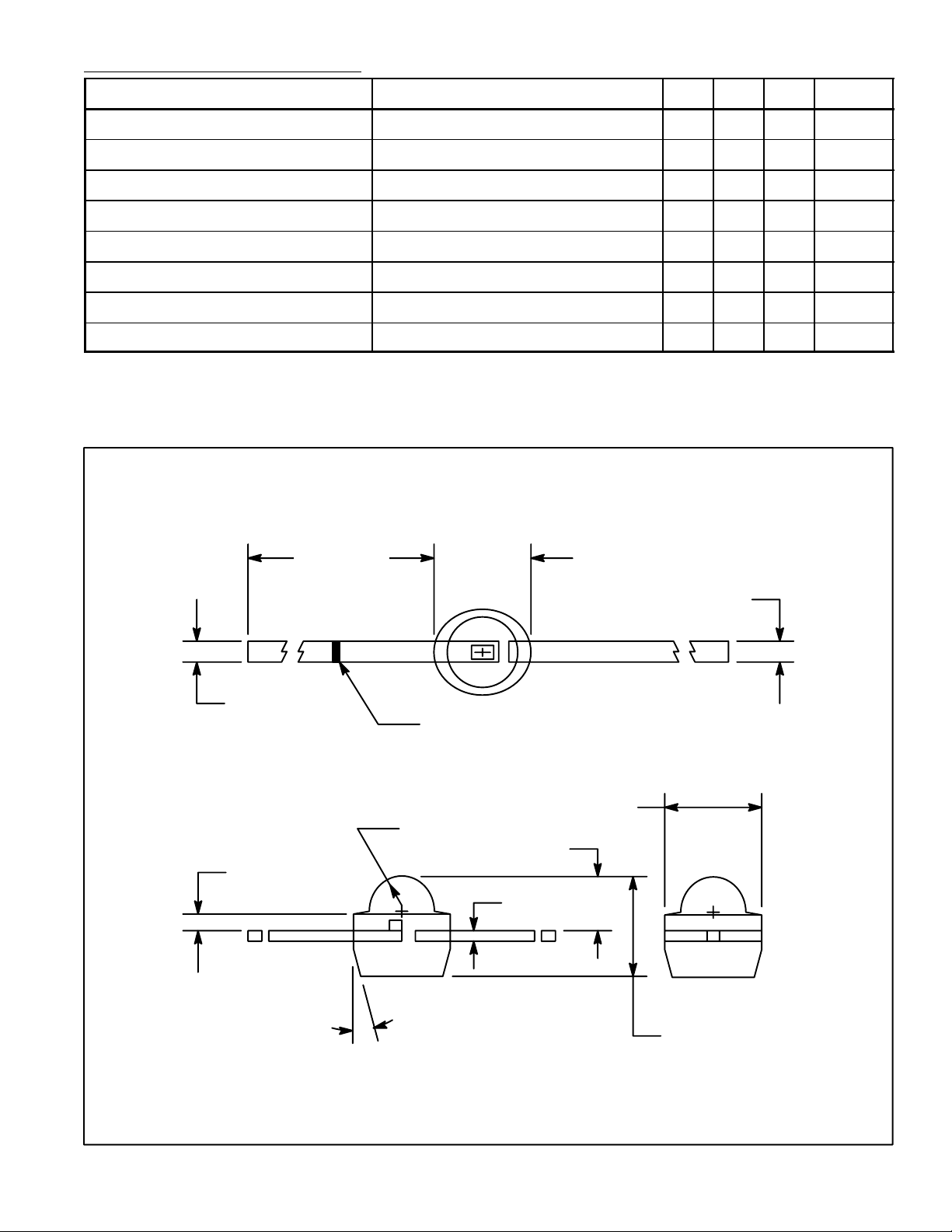
.025 (0.65)
.015 (0.39)
.250
(6.35)
Min
.100 (2.54)
.020 (.508)
Green Mark
Indicates Cathode (–)
.085 (2.18)
.038 (0.98) R
.055 (1.4)
.010 (.254)
15°
.095 (2.42)
 Loading...