

NTE NTE2732A Datasheet
NTE2732A
Integrated Circuit
32K (4K x 8) NMOS UV Erasable PROM
Description:
The NTE2732A is a 32,768–bits ultraviolet erasable and electrically programmable read–only
memory (EPROM) organized as 4,096 words by 8 bits and manufactured using N–Channel Si–Gate
MOS processing. With its single +5V power supply and with an access time of 200ns, the NTE2732A
is ideal for use with high performance +5V microprocessors such as the NTE3880.
The NTE2732A has an important feature which is the separate output control, Output Enable (OE)
from the Chip Enable control (CE). The OE control eliminates bus contention in multiple bus microprocessor systems.
The NTE2732A also features an standby mode which reduces the power dissipation without increasing access time. The active current is 125mA while the maximum standby mode is achieved by applying a TTL–high signal to the CE input.
Features:
D Fast Access Time: 200ns Max
D 0° to +70°C Standard Temperature Range
D Single +5V Power Supply
D Low Standby Current (35mA Max)
D Inputs and Outputs TTL Compatible During Read and Program
D Completely Static
Absolute Maximum Ratings: (Note 1)
All Input or Output Voltages with respect to GND, VI +6 to –0.6V. . . . . . . . . . . . . . . . . . . . . . . . . . . . .
Supply Voltage with respect to GND during Program, Vpp +22 to –0.6V. . . . . . . . . . . . . . . . . . . . . . .
Ambient Temperature under Bias, TA –10° to +80°C. . . . . . . . . . . . . . . . . . . . . . . . . . . . . . . . . . . . . . . .
Storage Temperature Range, T
–65° to +125°C. . . . . . . . . . . . . . . . . . . . . . . . . . . . . . . . . . . . . . . . . .
stg
Note 1. Stresses above those listed under “Absolute Maximum Ratings” may cause permanent
damage to the device. This is a stress rating only and functional operation of the device at
these or any other conditions above those indicated in the operational sections of this specification is not implied. Exposure to absolute maximum rating conditions for extended periods
may affect device reliability.
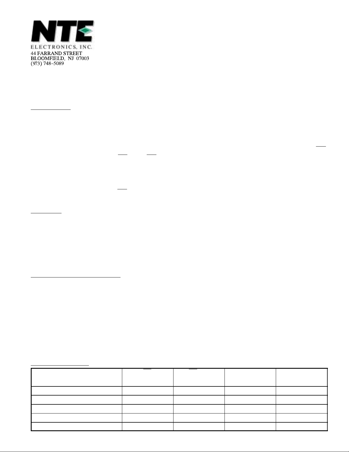
Operating Modes:
PINS CE OE/V
MODE (18) (20) (24) (9 – 11, 13–17)
READ V
STANDBY V
PROGRAM V
PROGRAM VERIFTY V
PROGRAM INHIBIT V
IH
IH
IL
Don’t Care +5 HIGH Z
IL
IL
pp
V
IL
V
PP
V
IL
V
PP
V
CC
+5 D
+5 D
+5 D
+5 HIGH Z
OUTPUTS
OUT
IN
OUT
Read Operation (DC and AC Conditions):
Operating Temperature Range, T
opr
0° to +70°C. . . . . . . . . . . . . . . . . . . . . . . . . . . . . . . . . . . . . . . . . . .
VCC Power Supply (Note 2, Note 3) 5V ± 5%. . . . . . . . . . . . . . . . . . . . . . . . . . . . . . . . . . . . . . . . . . . . . .
Vpp Voltage (Note 3) Vpp = V
. . . . . . . . . . . . . . . . . . . . . . . . . . . . . . . . . . . . . . . . . . . . . . . . . . . . . . . . .
CC
Note 2. VCC must b e applied s imultaneousl y with o r before VPP and r emoved sim ultaneously o r after VPP.
Note 3. V
may be connected directly to VCC except during programming. The supply current
PP
would then be the sum of I
CC
and I
PP1
.
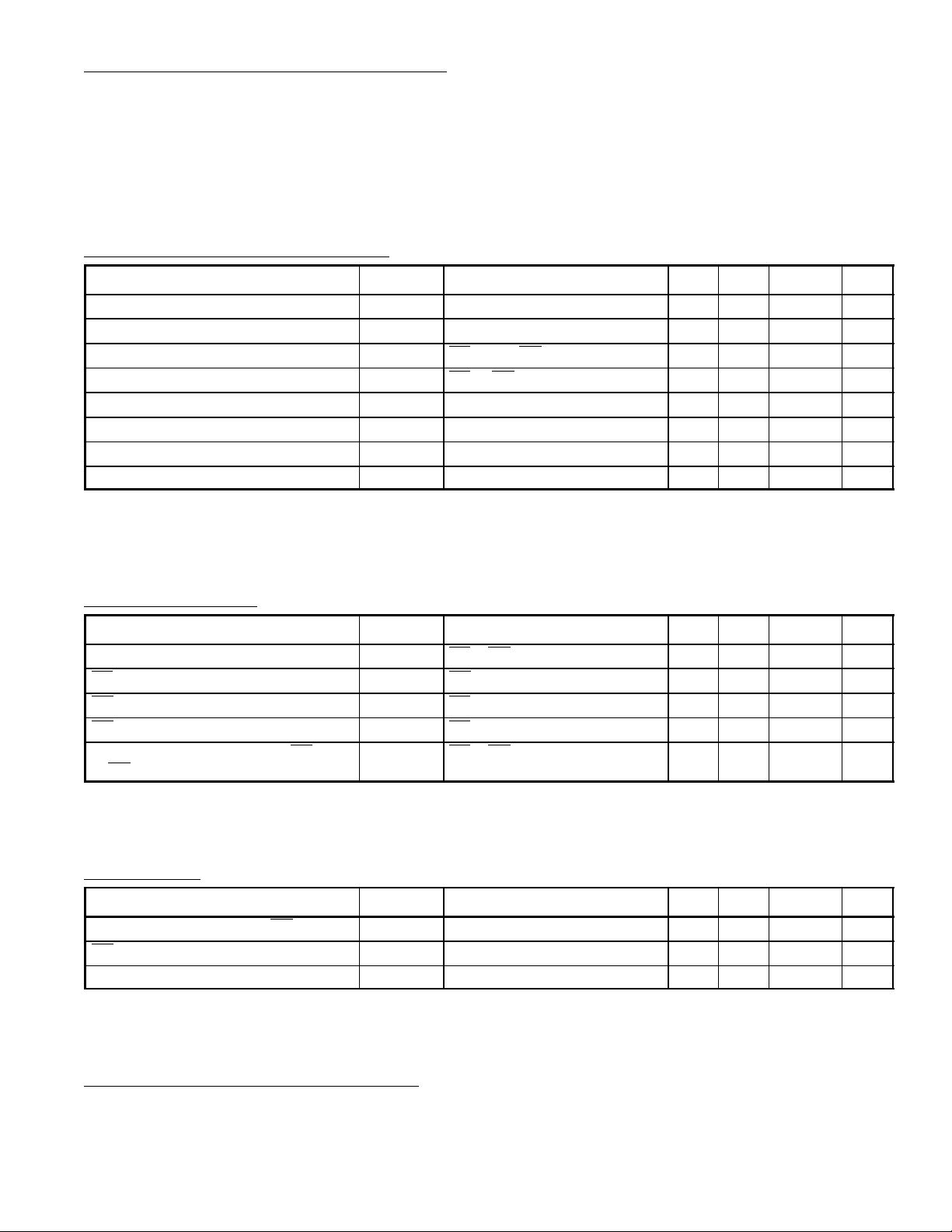
DC and Operating Characteristics:
Parameter Symbol Test Conditions Min Typ Max Unit
Input Load Current I
Output Leakage Current I
VCC Current Standby I
VCC Current Standby I
Input Low Voltage V
Input High Voltage V
Output Low Voltage V
Output High Voltage V
LI
LO
CC1
CC2
IL
IH
OL
OH
VIN = 5.5V – – 10 µA
V
= 5.5V – – 10 µA
OUT
CE = VIH, OE = VIL, Note 3 – – 35 mA
CE = OE = VIL, Note 3 – 70 125 mA
–0.1 – +0.8 V
2.0 VCC+1 V
IOL= 2.1mA – – 0.45 V
IOH = –400µA 2.4 – – V
Note 3. VPP may be connected directly to VCC except during programming. The supply current
would then be the sum of ICC and I
PP1
.
Note 4. Typical values are for TA = +25°C and nominal supply voltages.
AC Characteristics:
Parameter Symbol Test Conditions Min Typ Max Unit
Address to Output Delay t
CE to Output Delay t
OE to Output Delay t
OE High to Output Float t
Output Hold from Addresses CE or
OE whichever occurred first
ACC
CE
OE
DF
t
OH
CE = OE = V
OE = V
CE = V
CE = VIL, Note 5 0 – 60 ns
CE = OE = V
IL
IL
IL
IL
– – 200 ns
– – 200 ns
– – 100 ns
0 – – ns
Note 4. Typical values are for TA = +25°C and nominal supply voltages.
Note 5. This parameter is only sampled and is not 100% tested.
Capacitance: (TA = +25°C, f = 1MHz, Note 5 unless otherwise specified)
Parameter Symbol Test Conditions Min Typ Max Unit
Input Capacitance except OE/V
OE/Vpp Input Capacitance C
Output capacitance C
pp
C
IN1
IN2
OUT
VIN = 0 – 4 6 pF
VIN = 0 – – 20 pF
V
= 0 – 8 12 pF
OUT
Note 4. Typical values are for TA = +25°C and nominal supply voltages.
Note 5. This parameter is only sampled and is not 100% tested.
Read Operation (AC Test Conditions):
Output Load: 100pF + 1TTL Gate
Input Rise and Fall Times: ≤ 20ns
Input Pulse Levels: 0.45 to 2.4V
Timing Measurement Reference Levels: Inputs 0.8 and 2V/0.8 and 2V
 Loading...