

NTE NTE272, NTE273 Datasheet

NTE272 (NPN) & NTE273 (PNP)
Silicon Darlington Complementary
Power Amplifiers
Description:
The NTE272 (NPN) and NTE273 (PNP) are silicon complementary Power Amplifiers in a TO202 type
case designed for use in complementary amplifiers and driver applications.
Features:
D High DC Current Gain:
hFE= 25,000 (Min) @ IC = 200mA
= 15,000 (Min) @ IC = 500mA
D Collector–Emitter Breakdown Voltage:
V
(BR)CES
D Low Collector–Emitter Saturation Voltage:
V
CE(sat)
D Monolithic Construction for High Reliability
Absolute Maximum Ratings:
Collector–Emitter Voltage (Note 2), V
Collector–Emitter Voltage, V
Collector–Base Voltage, V
Emitter–Base Voltage, V
Collector Current, I
Total Power Dissipation (TA = +25°C), P
Derate above 25°C 8mW/°C. . . . . . . . . . . . . . . . . . . . . . . . . . . . . . . . . . . . . . . . . . . . . . . . . . . . . . .
Total Power Dissipation (TC = +25°C), P
Derate above 25°C 80mW/°C. . . . . . . . . . . . . . . . . . . . . . . . . . . . . . . . . . . . . . . . . . . . . . . . . . . . . .
Operating Junction Temperature Range, T
Storage Temperature Range, T
Thermal Resistance, Junction–to–Ambient, R
Thermal Resistance, Junction–to–Case, R
= 40V @ IC = 500mA
= 1.5V @ IC = 1A
CES
CB
EB
C
–55 to +150°C. . . . . . . . . . . . . . . . . . . . . . . . . . . . . . . . . . . . . . . . . . .
stg
CEO
40V. . . . . . . . . . . . . . . . . . . . . . . . . . . . . . . . . . . . . . . . . . . . . .
40V. . . . . . . . . . . . . . . . . . . . . . . . . . . . . . . . . . . . . . . . . . . . . . . . . . . . . .
50V. . . . . . . . . . . . . . . . . . . . . . . . . . . . . . . . . . . . . . . . . . . . . . . . . . . . . . . .
12V. . . . . . . . . . . . . . . . . . . . . . . . . . . . . . . . . . . . . . . . . . . . . . . . . . . . . . . . . .
2A. . . . . . . . . . . . . . . . . . . . . . . . . . . . . . . . . . . . . . . . . . . . . . . . . . . . . . . . . . . . . . . . .
D
D
J
thJA
thJC
–55 to +150°C. . . . . . . . . . . . . . . . . . . . . . . . . . . . . . . . . . .
125°C/W. . . . . . . . . . . . . . . . . . . . . . . . . . . . . . . . . .
12.5°C/W. . . . . . . . . . . . . . . . . . . . . . . . . . . . . . . . . . . .
1W. . . . . . . . . . . . . . . . . . . . . . . . . . . . . . . . . . . . . . . . . . . . . .
10W. . . . . . . . . . . . . . . . . . . . . . . . . . . . . . . . . . . . . . . . . . . .
Note 1. NTE273 is a discontinued device and no longer available.
Note 2. Due to the monolithic construction of this device, breakdown voltages of both transistor ele-
ments are identical. V
(BR)CES
by noise pickup. The voltage measured during the V
is tested in lieu of V
(BR)CEO
(BR)CES
in order to avoid errors caused
test is the V
(BR)CEO
of the output
transistor.
Electrical Characteristics: (TA = +25°C unless otherwise specified)
Parameter Symbol Test Conditions Min Typ Max Unit
OFF Characteristics
Collector–Emitter Breakdown Voltage V
Collector–Base Breakdown Voltage V
Emitter–Base Breakdown Voltage V
Collector Cutoff Current I
Emitter Cutoff Current I
(BR)CESIC
(BR)CBOIC
(BR)EBOIE
CBO
EBO
= 100µA, VBE = 0 40 – – V
= 100µA, IE = 0 50 – – V
= 10µA, IC = 0 12 – – V
VCB = 30V, IE = 0 – – 100 nA
VEB = 10V, IC = 0 – – 100 nA
ON Characteristics (Note 3)
DC Current Gain |hfe| IC = 200mA, VCE = 5V 25,000 65,000 150,000
IC = 500mA, VCE = 5V 15,000 35,000 –
IC = 1A, VCE = 5V 4,000 12,000 –
Collector–Emitter Saturation Voltage V
Base–Emitter Saturation Voltage V
Base–Emitter ON Voltage V
CE(sat)IC
BE(sat)IC
BE(ON)IC
= 1A, IB = 2mA – 1.2 1.5 V
= 1A, IB = 2mA – 1.85 2.0 V
= 1A, VCE = 5V – 1.7 2.0 V
Dynamic Characteristics
Small–Signal Current Gain h
FE
IC = 200mA, VCE = 5V,
1.0 3.2 –
f = 100MHz, Note 2
Collector–Base Capacitance C
VCB = 10V, IE = 0, f = 1MHz – 2.5 6.0 pF
cb
Note 3. Pulse test: Pulse Width ≤ 300µs, Duty Cycle ≤ 2.0%.
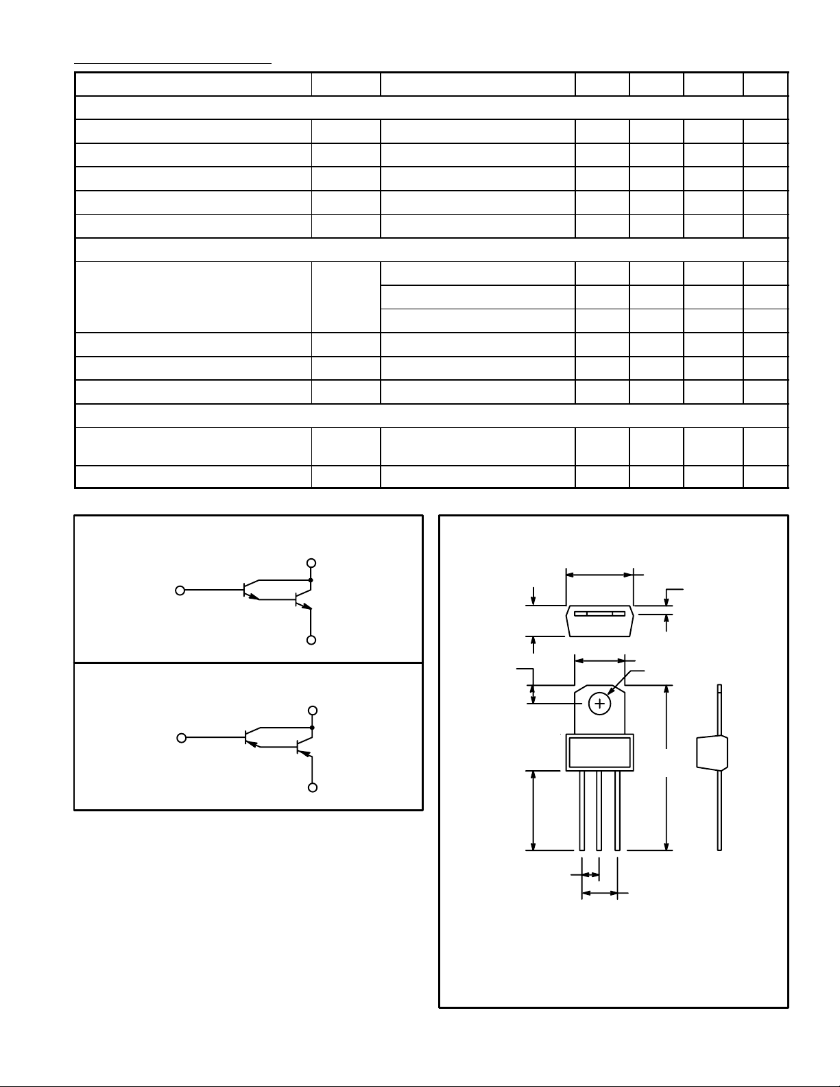
NTE272 Schematic
C
B
E
NTE273 Schematic
C
B
E
Uniwatt darlington transistors can be used in any
number of low power applications, such as relay
drivers, motor control and as general purpose
amplifiers. As an audio amplifier these devices,
when used as a complementary pair, can drive
3.5 watts into a 3.2ohm speaker using a 14 volt
supply with less than one per cent distortion. Because of the high gain the base drive requirement
is as low as 1mA in this application. They are also
useful as power drivers for high current application such as voltage regulators.
.218
(5.55)
.160
(4.06)
.475
(12.0)
Min
EBC
.100 (2.54)
Collector Connected to Tab
TO202N
.380 (9.65) Max
.050 (1.27)
.280 (7.25) Max
.128 (3.28) Dia
.995
(25.3)
.200 (5.08)
 Loading...