

NTE NTE2640 Datasheet
NTE2640
Silicon NPN Transistor
Color TV Horizontal Deflection Output
Features:
D High Speed
D High Collector–Emitter Breakdown Voltage
D High Reliability
D On–Chip Damper Diode
Absolute Maximum Ratings: (TA + 25°C unless otherwise specified)
Collector–Base Voltage, V
Collector–Emitter Voltage, V
Emitter–Base Voltage, V
Collector Current, I
C
Continuous 6A. . . . . . . . . . . . . . . . . . . . . . . . . . . . . . . . . . . . . . . . . . . . . . . . . . . . . . . . . . . . . . . . . . .
Pulse 15A. . . . . . . . . . . . . . . . . . . . . . . . . . . . . . . . . . . . . . . . . . . . . . . . . . . . . . . . . . . . . . . . . . . . . . .
Collector Dissipation, P
TA + 25°C 2W. . . . . . . . . . . . . . . . . . . . . . . . . . . . . . . . . . . . . . . . . . . . . . . . . . . . . . . . . . . . . . . . . . .
TC + 25°C 30W. . . . . . . . . . . . . . . . . . . . . . . . . . . . . . . . . . . . . . . . . . . . . . . . . . . . . . . . . . . . . . . . . .
Operating Junction Temperature, T
Storage Temperature Range, T
CBO
CEO
EBO
C
J
stg
1500V. . . . . . . . . . . . . . . . . . . . . . . . . . . . . . . . . . . . . . . . . . . . . . . . . . . . .
800V. . . . . . . . . . . . . . . . . . . . . . . . . . . . . . . . . . . . . . . . . . . . . . . . . . . . .
6V. . . . . . . . . . . . . . . . . . . . . . . . . . . . . . . . . . . . . . . . . . . . . . . . . . . . . . . . . .
+150°C. . . . . . . . . . . . . . . . . . . . . . . . . . . . . . . . . . . . . . . . . . . . . . .
–55° to +150°C. . . . . . . . . . . . . . . . . . . . . . . . . . . . . . . . . . . . . . . . . .
Electrical Characteristics: (TA + 25°C unless otherwise specified)
Parameter Symbol Test Conditions Min Typ Max Unit
Collector Cutoff Current I
Emitter Cutoff Current I
Collector–Emitter Sustaining Voltage V
Collector–Emitter Saturation Voltage V
Base–Emitter Saturation Voltage V
DC Current Gain h
Diode Forward Voltage V
Fall Time t
CBO
I
CES
EBO
CEO(sus)IC
CE(sat)IC
BE(sat)IC
FE
VCE = 800V, IE = 0 – – 10 µA
VCE = 1500V, RBE = 0 – – 1.0 mA
VEB = 4V, IC = 0 40 – – mA
= 100mA, IB = 0 800 – – V
= 3.15A, IB = 630mA – – 3.0 V
= 3.15A, IB = 630mA – – 1.5 V
VCE = 5V, IC = 500mA 10 – –
VCE = 5V, IC = 3.5A 5 – 8
IEC = 6A – – 2 V
F
VCC = 200V, VBE = –2V, IC = 2A,
f
IB1 = 400mA, IB2 = 800mA,
Pulse Width = 20µs, Duty Cycle ≤ 1%
– – 0.3 µs
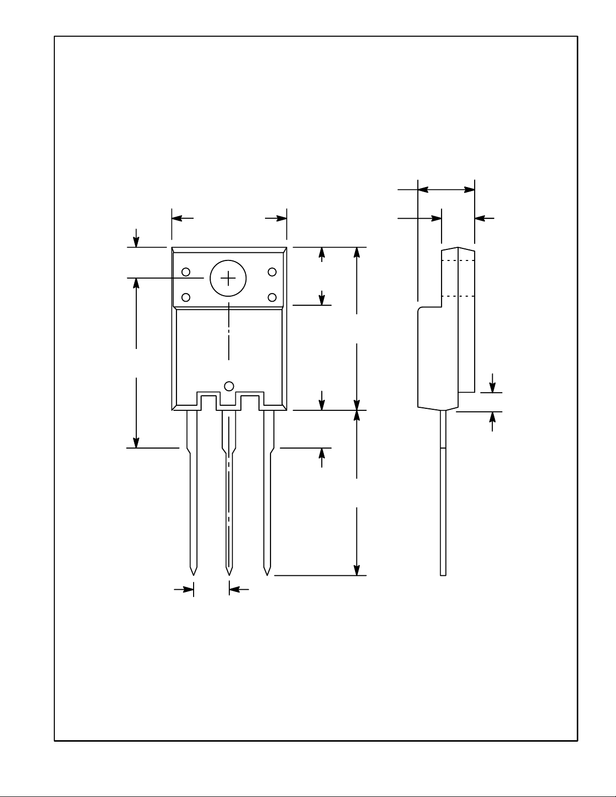
.177 (4.5)
.138
(3.5)
.634
(16.1)
.394 (10.0)
Isol
B E
C
.283
(7.2)
.142
(3.6)
.110 (2.8)
.630
(16.0)
.024
(0.6)
.551
(14.0)
.100 (2.54)
 Loading...