

NTE NTE2561 Datasheet
NTE2561
Silicon NPN Transistor
Video Amplifier
Features:
D High Gain–Bandwidth Product
D High Breakdown Voltage
D Large Current
D Small Reverse Transfer Capacitance
Applications:
D Wide–Band Amplifiers
Absolute Maximum Ratings: (TA = +25°C unless otherwise specified)
Collector–Base Voltage, V
Collector–Emitter Voltage, V
Emitter–Base Voltage, V
Collector Current, I
C
Continuous 500mA. . . . . . . . . . . . . . . . . . . . . . . . . . . . . . . . . . . . . . . . . . . . . . . . . . . . . . . . . . . . . . .
Peak (Pulse) 1.0A. . . . . . . . . . . . . . . . . . . . . . . . . . . . . . . . . . . . . . . . . . . . . . . . . . . . . . . . . . . . . . . .
Collector Dissipation, P
TA = +25°C 1.75W. . . . . . . . . . . . . . . . . . . . . . . . . . . . . . . . . . . . . . . . . . . . . . . . . . . . . . . . . . . . . . . .
TC = +25°C 15W. . . . . . . . . . . . . . . . . . . . . . . . . . . . . . . . . . . . . . . . . . . . . . . . . . . . . . . . . . . . . . . . .
Operating Junction Temperature, T
Storage Temperature Range, T
CBO
CEO
EBO
C
J
stg
100V. . . . . . . . . . . . . . . . . . . . . . . . . . . . . . . . . . . . . . . . . . . . . . . . . . . . . .
80V. . . . . . . . . . . . . . . . . . . . . . . . . . . . . . . . . . . . . . . . . . . . . . . . . . . . . .
3V. . . . . . . . . . . . . . . . . . . . . . . . . . . . . . . . . . . . . . . . . . . . . . . . . . . . . . . . . .
+150°C. . . . . . . . . . . . . . . . . . . . . . . . . . . . . . . . . . . . . . . . . . . . . . .
–55° to +150°C. . . . . . . . . . . . . . . . . . . . . . . . . . . . . . . . . . . . . . . . . .
Electrical Characteristics: (TA = +25°C unless otherwise specified)
Parameter Symbol Test Conditions Min Typ Max Unit
Collector Cutoff Current I
Emitter Cutoff Current I
DC Current Gain h
Gain–Bandwidth Product f
Output Capacitance C
Reverse Transfer Capacitance C
Collector–Emitter Saturation Voltage V
Base–Emitter Saturation Voltage V
Collector–Base Breakdown Voltage V
Collector–Emitter Breakdown Voltage V
Emitter–Base Breakdown Voltage V
CE(sat)IC
BE(sat)IC
(BR)CBOIC
(BR)CEOIC
(BR)EBOIE
CBO
EBO
FE
T
ob
VCB = 80V, IE = 0 – – 0.1 µA
VEB = 2V, IC = 0 – – 5.0 µA
VCE = 10V, IC = 50mA 30 – 200
VCE = 10V, IC = 100mA 20 – –
VCE = 10V, IC = 100mA – 1.2 – GHz
VCB = 30V, f = 1MHz – 4.4 – pF
VCB = 30V, f = 1MHz – 3.8 – pF
re
= 300mA, IB = 30mA – – 0.6 V
= 300mA, IB = 30mA – – 1.2 V
= 10µA, IE = 0 100 – – V
= 1mA, RBE = ∞ 80 – – V
= 100µA, IC = 0 3 – – V
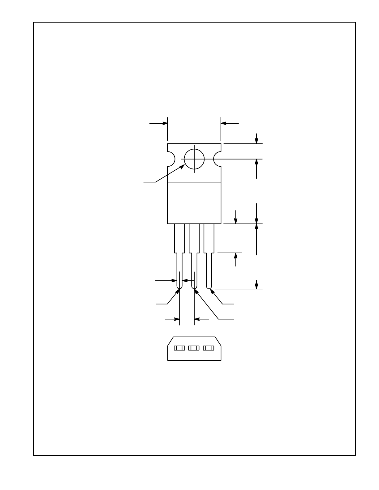
.420 (10.67)
Max
.110 (2.79)
.147 (3.75)
Dia Max
.070 (1.78) Max
Base
.100 (2.54) Collector/Tab
.500
(12.7)
Max
.250 (6.35)
Max
.500
(12.7)
Min
Emitter
 Loading...