

NTE NTE2510 Datasheet
NTE2510
Silicon NPNTransistor
High Frequency Video Output
Features:
D High Gain Bandwidth Product: fT = 2GHz
D High Current Capacity: IC = 500mA
Applications:
D High–Definition CRT Display Video Output
D Wide–Band Amp
Absolute Maximum Ratings: (TA = +25°C unless otherwise specified)
Collector–to–Base Voltage, V
Collector–to–Emitter Voltage, V
Emitter–to–Base Voltage, V
Collector Current, I
C
Continuous 500mA. . . . . . . . . . . . . . . . . . . . . . . . . . . . . . . . . . . . . . . . . . . . . . . . . . . . . . . . . . . . . . .
Peak 1000mA. . . . . . . . . . . . . . . . . . . . . . . . . . . . . . . . . . . . . . . . . . . . . . . . . . . . . . . . . . . . . . . . . . .
Collector Dissipation, P
C
TA = +25°C 1.3W. . . . . . . . . . . . . . . . . . . . . . . . . . . . . . . . . . . . . . . . . . . . . . . . . . . . . . . . . . . . . . . . .
TC = +25°C 5W. . . . . . . . . . . . . . . . . . . . . . . . . . . . . . . . . . . . . . . . . . . . . . . . . . . . . . . . . . . . . . . . . .
Operating Junction Temperature, T
Storage Temperature Range, T
CBO
CEO
EBO
J
stg
30V. . . . . . . . . . . . . . . . . . . . . . . . . . . . . . . . . . . . . . . . . . . . . . . . . . . .
20V. . . . . . . . . . . . . . . . . . . . . . . . . . . . . . . . . . . . . . . . . . . . . . . . . . .
3V. . . . . . . . . . . . . . . . . . . . . . . . . . . . . . . . . . . . . . . . . . . . . . . . . . . . . . .
+150°C. . . . . . . . . . . . . . . . . . . . . . . . . . . . . . . . . . . . . . . . . . . . . . .
–55° to +150°C. . . . . . . . . . . . . . . . . . . . . . . . . . . . . . . . . . . . . . . . . .
Electrical Characteristics: (TA = +25°C unless otherwise specified)
Parameter Symbol Test Conditions Min Typ Max Unit
Collector Cutoff Current I
Emitter Cutoff Current I
DC Current Gain h
Gain Bandwidth Product f
CBO
EBO
FE
T
VCB = 20V, IE = 0 – – 0.1 µA
VEB = 2V, IC = 0 – – 5.0 µA
VCE = 5V, IC = 50mA 60 – 120
VCE = 5V, IC = 500mA 20 – –
VCE = 5V, IC = 100mA – 2.0 – GHz
Electrical Characteristics (Cont’d): (TA = +25°C unless otherwise specified)
Parameter Symbol Test Conditions Min Typ Max Unit
Output Capacitance C
Reverse Transfer Capacitance C
Collector–Emitter Saturation Voltage V
Base–Emitter Saturation Voltage V
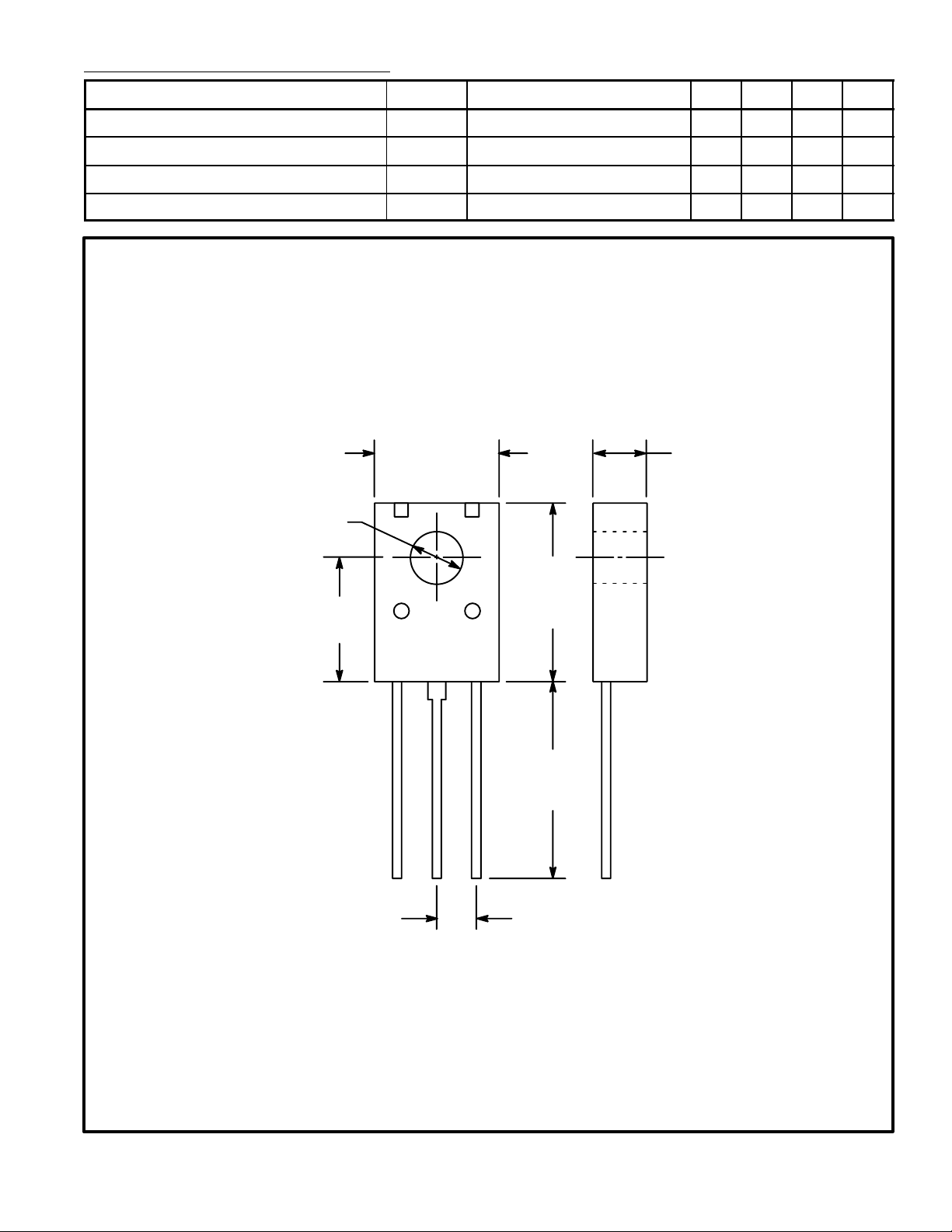
.118 (3.0)
Dia
CE(sat)IC
BE(sat)IC
.315 (8.0)
ob
VCB = 10V, f = 1MHz – 6.0 – pF
VCB = 10V, f = 1MHz – 4.6 – pF
re
= 300mA, IB = 30mA – 0.3 0.8 V
= 300mA, IB = 30mA – 0.9 1.2 V
.130
(3.3)
.295
(7.5)
.433
(11.0)
ECB
.610
(15.5)
.094 (2.4)
 Loading...