

NTE NTE2426, NTE2427 Datasheet
NTE2426 (NPN) & NTE2427 (PNP)
Silicon Complementary Transistors
Darlington Switch
Description:
The NTE2426 and NTE2427 are silicon planer Darlington transistors in a SOT–89 type surface mount
package designed for use in industrial switching applications such as print hammer, solenoid, relay,
and lamp drivers.
Absolute Maximum Ratings:
Collector–Base Voltage (Open Emitter), V
Collector–Emitter Voltage, V
CER
Emitter–Base Voltage (Open Collector), V
Collector Current, I
C
CBO
EBO
Continuous 500mA. . . . . . . . . . . . . . . . . . . . . . . . . . . . . . . . . . . . . . . . . . . . . . . . . . . . . . . . . . . . . . .
Peak 1.5A. . . . . . . . . . . . . . . . . . . . . . . . . . . . . . . . . . . . . . . . . . . . . . . . . . . . . . . . . . . . . . . . . . . . . .
Base Current, I
Total Power Dissipation (T
Operating Junction Temperature (Note 2), T
Storage Temperature Range, T
Thermal Resistance, Junction–to–Ambient (Note 1, Note 2), R
Thermal Resistance, Junction–to–Tab (Note 2), R
Note 1. Device mounted on a ceramic substrate; area = 2.5cm
B
≤ +25°C, Note 1), P
A
stg
tot
J
–65° to +150°C. . . . . . . . . . . . . . . . . . . . . . . . . . . . . . . . . . . . . . . . . .
thJA
thJTAB
2
, thickness = 0.7mm.
Note 2. Based on maximum average junction temperature in line with common industrial practice.
The resulting higher junction teperature of the output transistor part is taken into account.
90V. . . . . . . . . . . . . . . . . . . . . . . . . . . . . . . . . . . . . . . . . .
80V. . . . . . . . . . . . . . . . . . . . . . . . . . . . . . . . . . . . . . . . . . . . . . . . . . . . . .
5V. . . . . . . . . . . . . . . . . . . . . . . . . . . . . . . . . . . . . . . . . . .
100mA. . . . . . . . . . . . . . . . . . . . . . . . . . . . . . . . . . . . . . . . . . . . . . . . . . . . . . . . . . . . . . . .
1W. . . . . . . . . . . . . . . . . . . . . . . . . . . . . . . . . . . . . .
+150°C. . . . . . . . . . . . . . . . . . . . . . . . . . . . . . . . . . . . . . .
125K/W. . . . . . . . . . . . . . . . . . . .
10K/W. . . . . . . . . . . . . . . . . . . . . . . . . . . . . .
Electrical Characteristics: (TJ = +25°C unles otherwise specified)
Parameter Symbol Test Conditions Min Typ Max Unit
Collector Cutoff Current I
Emitter Cutoff Current I
DC Current Gain h
CES
EBO
V
= 80V, VBE = 0 – – 10 µA
CER
VEB = 4V, IC = 0 – – 10 µA
VCE = 10V, IC = 150mA, Note 3 1000 – –
FE
VCE = 10V, IC = 500mA, Note 3 2000 – –
Note 3. Measured under pulsed conditions.
Electrical Characteristics (Cont’d): (TJ = +25°C unles otherwise specified)
Parameter Symbol Test Conditions Min Typ Max Unit
Collector–Emitter Saturation Voltage V
Base–Emitter Saturation Voltage V
Turn–On Time t
Turn–Off Time t
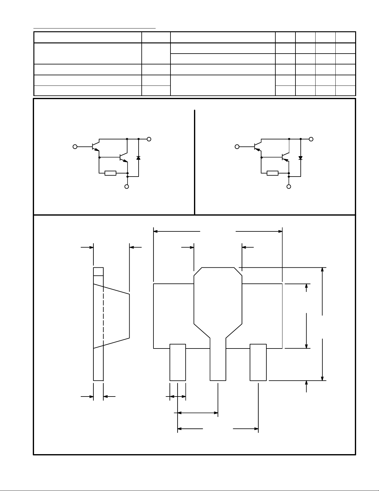
NTE2426
NPN
B
E
CE(sat)IC
= 500mA, IB = 0.5mA – – 1.3 V
IC = 500mA, IB = 0.5mA, TJ = +150°C – – 1.3 V
BE(sat)IC
on
off
= 500mA, IB = 0.5mA – – 1.9 V
IC = 500mA, I
Schematic Diagram
C
Bon
= –I
= 0.5mA – 400 – ns
Boff
– 1500 – ns
NTE2427
PNP
C
B
E
.015 (0.32)
.059 (1.5)
.020 (.508)
.174 (4.42)
.067 (1.7)
ECB
.096
(2.46)
.161
(4.1)
.041
(1.05)
Min
.059 (1.5)
.118 (3.0)
Bottom View
 Loading...