

NTE NTE2362, NTE2361 Datasheet
NTE2361 (NPN) & NTE2362 (PNP)
Silicon Complementary Transistors
High Speed Switch
Description:
The NTE2361 (NPN) and NTE2362 (PNP) complimentary silicon transistors are designed for general–purpose amplifier and high speed switching applications. The high gain of these devices makes
it possible for them to be driven directly from integrated circuits.
Features:
D Very Small–Sized Package
D High Breakdown Voltage: V
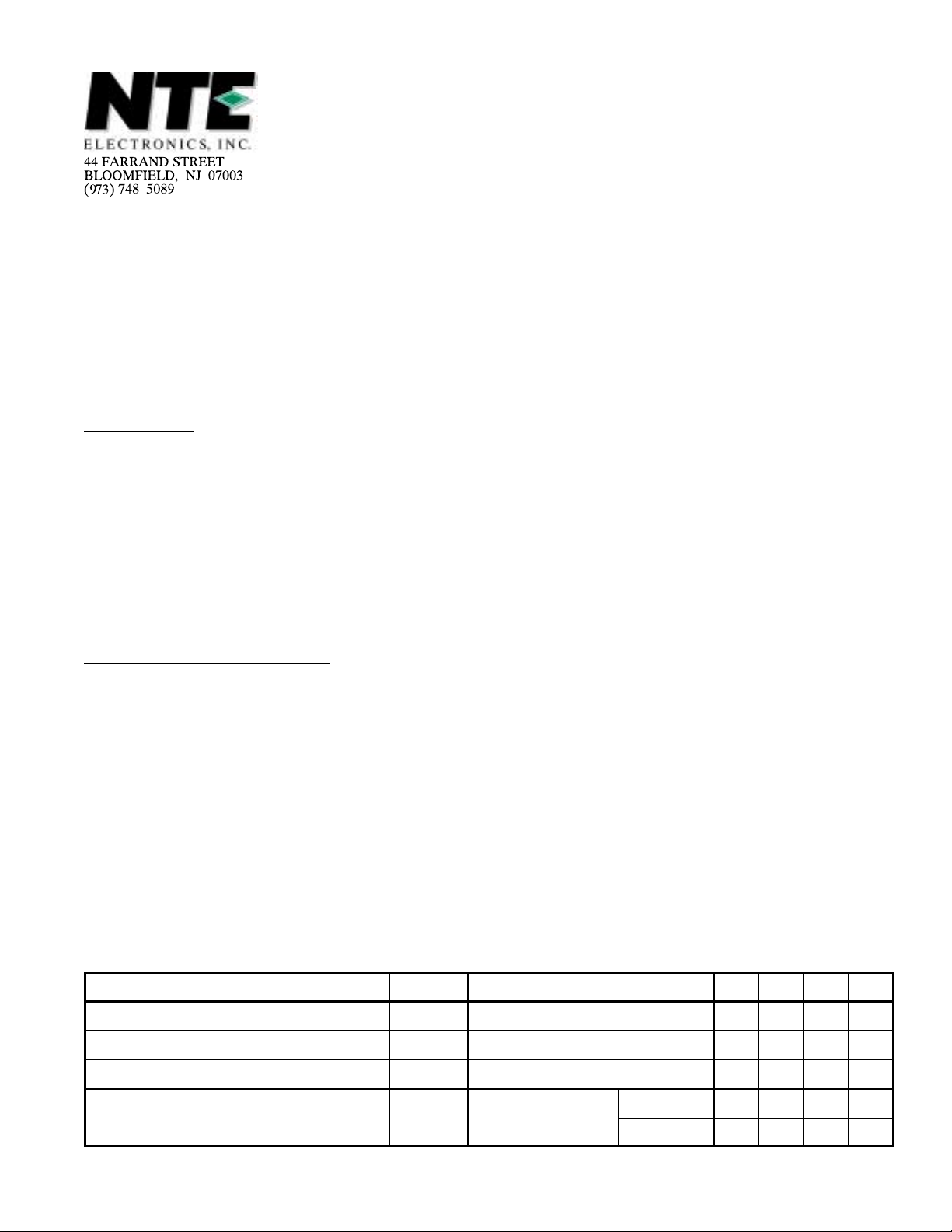
Absolute Maximum Ratings
Collector–Base Voltage, V
Collector–Emitter Voltage, V
Emitter–Base Voltage, V
Collector Current, I
C
: (TA = +25°C unless otherwise specified)
CBO
CEO
EBO
CEO
= 50V
Continuous 500mA. . . . . . . . . . . . . . . . . . . . . . . . . . . . . . . . . . . . . . . . . . . . . . . . . . . . . . . . . . . . . . .
Peak 800mA. . . . . . . . . . . . . . . . . . . . . . . . . . . . . . . . . . . . . . . . . . . . . . . . . . . . . . . . . . . . . . . . . . . .
Collector Dissipation, P
Operating Junction Temperature Range, T
Storage Temperature Range, T
C
J
stg
Note 1. For PNP device (NTE2362), voltage and current values are negative.
Electrical Characteristics
Parameter Symbol Test Conditions Min Typ Max Unit
Collector Cutoff Current I
Emitter Cutoff Current I
DC Current Gain h
Gain Bandwidth Product f
: (TC = +25°C unless otherwise specified)
CBO
EBO
FE
T
VCB = 40Vdc, IE = 0 – – 0.1 µA
VBE = 4Vdc – – 0.1 µA
VCE = 5V, IC = 10mA 200 – 400
VCE = 10V,
IC = 50mA
NTE2361 – 200 – MHz
NTE2362 – 300 – MHz
60V. . . . . . . . . . . . . . . . . . . . . . . . . . . . . . . . . . . . . . . . . . . . . . . . . . . . . . .
50V. . . . . . . . . . . . . . . . . . . . . . . . . . . . . . . . . . . . . . . . . . . . . . . . . . . . . .
5V. . . . . . . . . . . . . . . . . . . . . . . . . . . . . . . . . . . . . . . . . . . . . . . . . . . . . . . . . .
300mW. . . . . . . . . . . . . . . . . . . . . . . . . . . . . . . . . . . . . . . . . . . . . . . . . . . . . . . .
–55° to +150°C. . . . . . . . . . . . . . . . . . . . . . . . . . . . . . . . . .
–55° to +150°C. . . . . . . . . . . . . . . . . . . . . . . . . . . . . . . . . . . . . . . . . .
Electrical Characteristics (Cont’d): (TC = 25°C unless otherwise specified)
Parameter Symbol Test Conditions Min Typ Max Unit
Output Capacitance C
ob
VCB = 10Vdc,
NTE2361 – 5.6 – pF
f = 1MHz
NTE2362 – 3.7 – pF
Collector–Emitter Saturation Voltage V
CE(sat)IC
= 100mA,
NTE2361 – 0.15 0.4 V
IB = 10mA
NTE2362 – 0.1 0.3 V
Base–Emitter Saturation Voltage V
Collector–Base Breakdown Voltage V
Collector–Emitter Breakdown Voltage V
Emitter–Base Breakdown Voltage V
BE(sat)IC
(BR)CBOIC
(BR)CEOIC
(BR)EBOIE
Rise Time t
Storage Time t
Fall Time t
on
stg
f
= 100mA, IB = 10mA – 0.8 1.2 V
= 10µA, IE = 0 60 – – V
= 100µA, RBE = ∞ 50 – – V
= 10µA, IC = ∞ 5 – – V
VCC = 20V,
– 70 – ns
IC = 100mA,
= 10mA,
I
B1
B1
IB2 = 100mA
NTE2361 – 50 – ns
– 400 – ns
NTE2362 – 70 – ns
Note 1. For PNP device (NTE2362), voltage and current values are negative.
Note 2. Conditions apply to both except where noted.
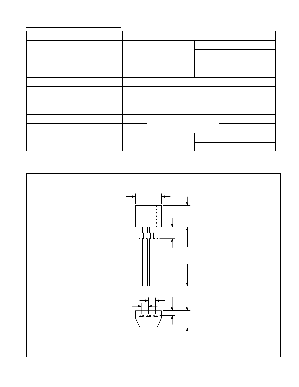
.050 (1.27)
.050 (1.27)
.165 (4.2)
Max
.126
(3.2)
Max
.071
(1.8)
.500
(12.7)
Max
ECB
.035 (0.9)
.102
(2.6)
Max
 Loading...