

NTE NTE2102 Datasheet
NTE2102
Integrated Circuit
NMOS, 1K Static RAM (SRAM), 350ns
Description:
The NTE2101 is a high–speed 1024 x 1 bit static random access read/write memory in a 16–Lead
DIP type package designed using N–Channel depletion mode silicon gate technology. Static storage
cells eliminate the need for clock or refresh circuitry.
Low threshold silicon gate N–Channel technology allows complete DTL/TTL compatibility of all inputs
and outputs as well as a single 5V supply. The separate chip enable input (CE
allows easy memory expansion by OR–tying individual devices to a data bus. Data in and data out
have the same polarity.
Features:
D Single 5V Supply
D All Inputs and Outputs Directly DTL/TTL Compatible
D Static Operation – No Clocks or Refresh
D All Inputs Protected Against Static Charge
D 350ns Access Time
) controlling the output
Absolute Maximum Ratings:
(Note 1)
Voltage at Any Pin 0.5V to +7V. . . . . . . . . . . . . . . . . . . . . . . . . . . . . . . . . . . . . . . . . . . . . . . . . . . . . . . . . . .
Power Dissipation, P
Storage Temperature Range, T
D
stg
Lead Temperature (During Soldering, 10sec), T
–65° to +150°C. . . . . . . . . . . . . . . . . . . . . . . . . . . . . . . . . . . . . . . . . .
L
1W. . . . . . . . . . . . . . . . . . . . . . . . . . . . . . . . . . . . . . . . . . . . . . . . . . . . . . . . . . . . . .
+300°C. . . . . . . . . . . . . . . . . . . . . . . . . . . . . . . . . . . .
Note 1. “Abso l u t e Maximu m Ratin gs ” are t h o s e values beyon d which the d e vi c e may b e permanently
damaged. They do not mean the device may be operated at these values.
Recommended Operating Conditions:
Parameter Symbol Test Conditions Min Typ Max Unit
Supply Voltage V
Operating Ambient Temperature T
Input Low Voltage V
Input High Voltage V
CC
A
IL
IH
4.75 – 5.25 V
0 – +70 °C
–0.5 – 0.8 V
2.0 – V
CC
V
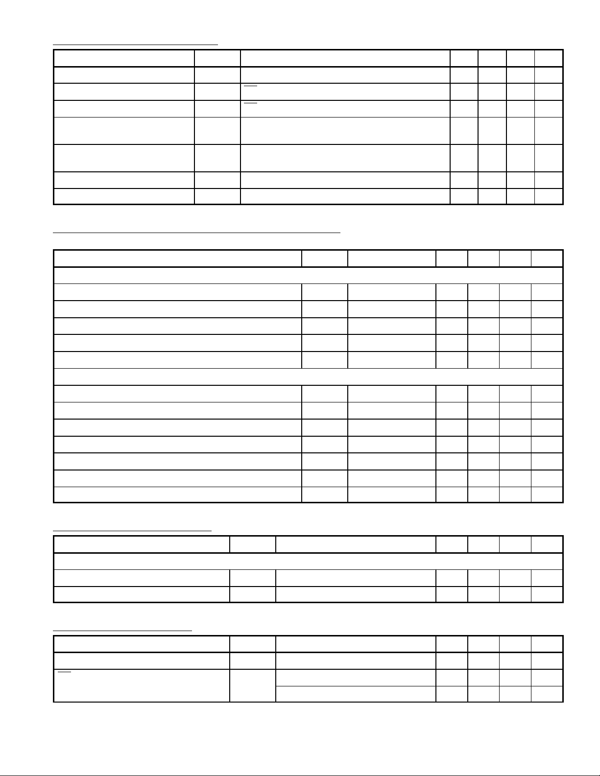
DC Electrical Characteristics: (TA = 0° to +70°C, VCC = 5V ±5% unless otherwise specified)
Parameter Symbol Test Conditions Min Typ Max Unit
Input Load Current I
Output Leakage Current, High I
Output Leakage Current, Low I
Power Supply Current I
Power Supply Amp I
Output Low Voltage V
Output High Voltage V
LI
LOH
LOL
CC
CC
OL
OH
VIN = 0 to 5.25V – – 10 µA
CE = 2V, V
CE = 2V, V
All Inputs = 5.25V, Data Output Open,
T
= +25°C
A
All Inputs = 5.25V, Data Output Open,
= 0°C
T
A
= 2.4V – – 5 µA
OUT
= 0.4V – – –10 µA
OUT
– – 45 mA
– – 50 mA
IOL = 3.2mA – – 0.4 V
IOH = –200µA 2.4 – – V
AC Electrical Characteristics (With Standard Load): (TA = 0° to +70°C, VCC = 5V ±5% unless
otherwise specified)
Parameter Symbol Test Conditions Min Typ Max Unit
Read Cycle
Read Cycle t
Access Time t
Chip Enable to Output Time t
Previous Read Data Valid with Respect to Address t
Previous Read Data Valid with Respect to Chip Enable t
Write Cycle
RC
A
CO
OH1
OH2
350 – – ns
– – 350 ns
– – 150 ns
40 – – ns
0 – – ns
Write Cycle t
Address to Write Set–Up t
Write Pulse Width t
Write Recovery Time t
Data Set–Up Time t
Data Hold Time t
Chip Enable to Write Set–Up t
WC
AW
WP
WR
DW
DH
CW
350 – – ns
20 – – ns
150 – – ns
0 – – ns
125 – – ns
0 – – ns
150 – – ns
AC Electrical Characteristis: (TA = +25°C, f = 1MHz unless otherwise specified)
Parameter Symbol Test Conditions Min Typ Max Unit
Capacitance
Input Capacitance C
Output Capacitance C
OUT
All Inputs VIN = 0V – 3 5 pF
IN
VO = 0V – 4 6 pF
Standby Characteristics: (TA = 0° to +70°C, Note 2 unless otherwise specified)
Parameter Symbol Test Conditions Min Typ Max Unit
VCC in Standby V
CE Bias in Standby V
PD
CES
2 ≤ VPD ≤ VCCmax 2.0 – – V
1.5 ≤ VPD ≤ 2 V
1.5 – – V
PD
– – V
Note 2. Typical values at TA = +25°C.
 Loading...