

NTE NTE2062 Datasheet
Integrated Circuit
PMOS Digital Alarm Clock
Features:
D Single–Chip ED MOS LSI
D LED Direct Drive by Time–Sharing (Duplex)
D Wide Operating Voltage Range
D Alarm on a 24–Hour Basis
D Two Selections of Time Format:
AM/PM 12–Hour Basis & 24–Hour Basis
D On–Chip CR Oscillator for Battery Backup
D 50Hz or 60Hz Reference Frequency
NTE2062
D Automatic Advance Capable:
“Hours”, “Minutes”
D Sleep Timer:
Max. 59 Minutes or 1Hour, 59 Minutes
D Repeatedly Usable Snooze
D Power Failure Indicator
D 900Hz Output for Alarm Tone
Functions:
D Real Time Display
D Alarm with Snooze
Applications:
D Alarm Clock
D Clock Radio
D Sleep Timer
Absolute Maximum Ratings: (VSS = 0, TA = +25°C unless otherwise specified)
Maximum Supply Voltage, VDDmax –15 to +0.3V. . . . . . . . . . . . . . . . . . . . . . . . . . . . . . . . . . . . . . . . . . .
Input Voltage, V
IN
50/60Hz –15 to +0.3V. . . . . . . . . . . . . . . . . . . . . . . . . . . . . . . . . . . . . . . . . . . . . . . . . . . . . . . . . . . . .
Other Than 50/60Hz –15 to +0.3V. . . . . . . . . . . . . . . . . . . . . . . . . . . . . . . . . . . . . . . . . . . . . . . . . .
Output Voltage, V
OUT
Input Clamp Current, I
IN
–15 to +0.3V. . . . . . . . . . . . . . . . . . . . . . . . . . . . . . . . . . . . . . . . . . . . . . . . . . . . . . .
–0.4 to +0.4mA. . . . . . . . . . . . . . . . . . . . . . . . . . . . . . . . . . . . . . . . . . . . . . . . . . .
Allowable Power Dissipation (TA = +70°C), PDmax 700mW. . . . . . . . . . . . . . . . . . . . . . . . . . . . . . . . . .
Operating Temperature Range, T
Storage Temperature Range, T
stg
opr
–30° to +70°C. . . . . . . . . . . . . . . . . . . . . . . . . . . . . . . . . . . . . . . . .
–55° to +125°C. . . . . . . . . . . . . . . . . . . . . . . . . . . . . . . . . . . . . . . . . .
Allowable Operating Ranges: (VSS = 0, TA = +25°C unless otherwise specified)
Parameter Symbol Test Conditions Min Typ Max Unit
Supply Voltage V
Input “HIGH” Level Voltage V
DD
IH
50/60Hz Input –1.0 – – V
Other Than 50/60Hz Input –1.5 – – V
–14 – –7.5 V
Input “LOW” Level Voltage V
Input Voltage on 50/60Hz V
AC–IN
50/60Hz – – VDD+2 V
IL
Other Than 50/60Hz – – VDD+2 V
Referenced to V
SS
V
LED
– – V
Electrical Characteristics: (VDD = –12V, TA = +25°C unless otherwise specified)
Parameter Symbol Test Conditions Min Typ Max Unit
Input “HIGH” Level Current I
Input “LOW” Level Current I
Output “HIGH” Level Current I
Output Leakage Current I
Power Failure Detect Voltage V
Current Dissipation I
Stability of Oscillator for Backup F
Accuracy of Oscillator for Backup F
OH
OF
CC
VIN = VSS, 50/60Hz – – 10 µA
IH
VIN = VDD, Input Pins other than 50/60Hz – – 20 µA
VIN = V
IL
50/60Hz – – 10 µA
DD,
VIN = VDD, Input Pins other than 50/60Hz – – 10 µA
Alarm Out, Sleep Out, VOH = VSS–1V 5 – – mA
10’s Hr ag & de (24Hr Mode), V
OUT
=
36 – – mA
VSS–1V
Segment Outputs other than above,
V
= VSS–1V
OUT
Alarm Out, Sleep Out, V
10’s Hr ag & de (24Hr Mode), V
Segment Outputs other than above,
V
= V
OUT
DD
DD
Output: OFF, Input with Pull–Down
OUT
= V
DD
OUT
= V
DD
18 – – mA
– – 10 µA
– – 20 µA
– – 20 µA
–7.5 –5.0 – V
– 5 7 mA
Resistor: Open
Typical value, 900Hz, VDD = –9V ±10% –10 – +10 %
S
Typical value, 900Hz, VDD = –9V ±10% –10 – +10 %
A
Operation Description:
50Hz/60Hz Input:
The On–Chip Schmitt Trigger circuit allows a simple RC filter at the input to remove possible line voltage transients. An internal pull–up resistor is provided.
CR Input: (Note 1)
When AC power–down occurs, the time counter enters the “hold” mode and the on–chip clock oscillator starts operating immediately. I f there is no input at “50/60Hz input” during 3–clock period, this oscillator controls the time counter advance instead of “50/60Hz input”. The values of CR determine the
frequency of the on–chip clock oscillator. All segment outputs are of f during backup operation. If the
backup OSC is used at the power–down mode, “50/60Hz input” must be open or at VSS level.
50/60Hz Select Input:
Connecting “50/60Hz select” to VSS enables 50Hz operation. For 60Hz operating, “50/60Hz select”
is left unconnected: Pull–down to VDD is provided by the internal pull–down resistor.
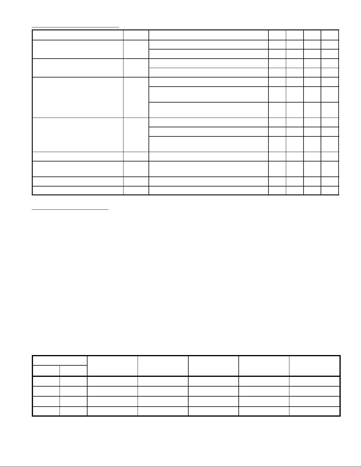
Display Mode Select Input (Alarm Display/Sleep Display):
The internal pull–down resistor allows the use of 2 SPST (single–pole single–throw) switches to select
4 display modes listed in Table 1.
Table 1. Display Mode
Select Input
Alarm Sleep
Display Mode Digit No.1 Digit No. 2 Digit No. 3 Digit No. 4
N.C. N.C. Time Display 10’s Hour, AM/PM Hour 10’s Minute Minute
V
SS
N.C. V
V
SS
N.C. Alarm Display 10’s Hour, AM/PM Hour 10’s Minute Minute
SS
V
SS
Sleep Display Blanked Hour 10’s Minute Minute
Seconds Display Blanked Minute 10’s Second Second
Note 1. If VSS is applied to 2 input of “alarm display” and “sleep display” simultaneously, the seconds
display mode is entered.
 Loading...