

NTE NTE1956 Datasheet
NTE1956
Integrated Circuit
Positive 3 Terminal Voltage Regulator,
Low Dropout Voltage, 24V, 1A
Description:
The NTE1956 is a positive voltage regulator in a TO220 type package with a low input/output voltage.
This device i s s uitable f or l ow –voltage, battery–driven equipment, a nd home appliances a nd industrial
equipment with great fluctuation of the supply voltage.
Features:
D Minimum Input/Output Voltage Difference: 0.5V Typ
D On–Chip Overcurrent Limiter
D On–Chip Thermal Protection Circuit
D On–Chip Inrush Current Protection Circuit at the time of Input Voltage Start–Up
D On–Chip Input Short–Circuit Protection Circuit (When the Input Pin is Short–Circuited to the
Ground, the Circuit Between Pin1 and Pin3 is Shut Down to Prevent Current Flow)
Applications:
D Power Supply Equipment
Absolute Maximum Ratings: (TA = +25°C unless otherwise specified)
Supply Voltage (Note 1), V
Supply Current (Note 2), I
Power Dissipation (Note 3), P
Operating Ambient Temperature Range, T
Storage Junction Temperature Range, T
IN
IN
D
opr
stg
Thermal Resistance, Junction–to–Ambient, R
Thermal Resistance, Junction–to–Case, R
thJC
–30° to +85°C. . . . . . . . . . . . . . . . . . . . . . . . . . . . . . . . . .
–55° to +150°C. . . . . . . . . . . . . . . . . . . . . . . . . . . . . . . . . .
thJA
30V. . . . . . . . . . . . . . . . . . . . . . . . . . . . . . . . . . . . . . . . . . . . . . . . . . . . . . . . .
2.4A. . . . . . . . . . . . . . . . . . . . . . . . . . . . . . . . . . . . . . . . . . . . . . . . . . . . . . . . .
15W. . . . . . . . . . . . . . . . . . . . . . . . . . . . . . . . . . . . . . . . . . . . . . . . . . . . . .
65°C/W. . . . . . . . . . . . . . . . . . . . . . . . . . . . . . . . . . . .
5°C/W. . . . . . . . . . . . . . . . . . . . . . . . . . . . . . . . . . . . . . .
Note 1. At the application of VIN = 30V, the overvoltage protection may be operated by the ASO
protection circuit, leading to the output shut down.
Note 2. The current value does not exceed this criterion because of the on–chip current limiter.
Note 3. The internal circuit shuts off the output when TJ ≤ +150°C (design value).
Recommended Operating Conditions: (IO = 500mA, TA = +25°C unless otherwise specified)
Parameter Symbol Test Conditions Min Typ Max Unit
Operating Supply Voltage Range V
IN
21.5 – 29.5 V
Electrical Characteristics: (VIN = 25.5V, IO = 500mA, TA = +25°C unless otherwise specified)
Parameter Symbol Test Conditions Min Typ Max Unit
Output Voltage V
OUT
Line Regulation REG
Load Regulation REG
Input Dependency of Bias Current DI
Load Dependency of Bias Current DI
Bias Current at No Load I
Bias Current Before the
Bias(IN)VIN
Bias(LOA)IO
Bias
I
rush
Regulation Starts
Minimum I/O Voltage Difference V
Peak Output Current I
DIF(min)
O(Peak)
Ripple Rejection Ratio RR VIN = 25.5V to 27.5V, IO = 100mA,
Design Reference Data (Note 5)
Output Short–Circuit Current I
Thermal Protection Operating
O(Short)
T
J(TH)
Temperature
Output Voltage Temperature
a TJ = +25° to +125°C – –40 – ppm/°C
Coefficient
TJ = +25°C 23.28 24.0 24.72 V
VIN = 25.5V to 29.5V, TJ = +25°C – 9.6 96 mV
IN
LOAVIN
= 25.5V, IO = 0 to 1200mA,
– 120 480 mV
TJ = +2 5°C
= 25.5V to 29.5V, TJ = +25°C – 1 10 mA
= 0 to 1200mA, TJ = +25°C – 10 50 mA
IO = 0mA – 2.6 5.0 mA
VIN = 21.6V, IO = 0mA – 3 5 mA
VIN = 21.6V,
TJ = +25°C
IO = 500mA – 0.4 0.6 V
IO = 1200mA – 0.5 1.0 V
VIN = 25.5V, TJ = +2 5°C, Note 4 1.2 1.8 2.4 A
36 56 – dB
f= 120Hz
VIN = 30V, TJ = +25°C, Shorted Load – 10 – mA
VIN = 25.5V – 150 – °C
Note 4. Th is c u r r en t e x c eeds PDmax because i t i s a p ar ameter d uring a bnor mal ( overcur rent) o perati on.
Note 5. Th e charact eristic e lis ted are theoretical values b ased o n t he I C d esign a nd a re n ot g uaranteed.
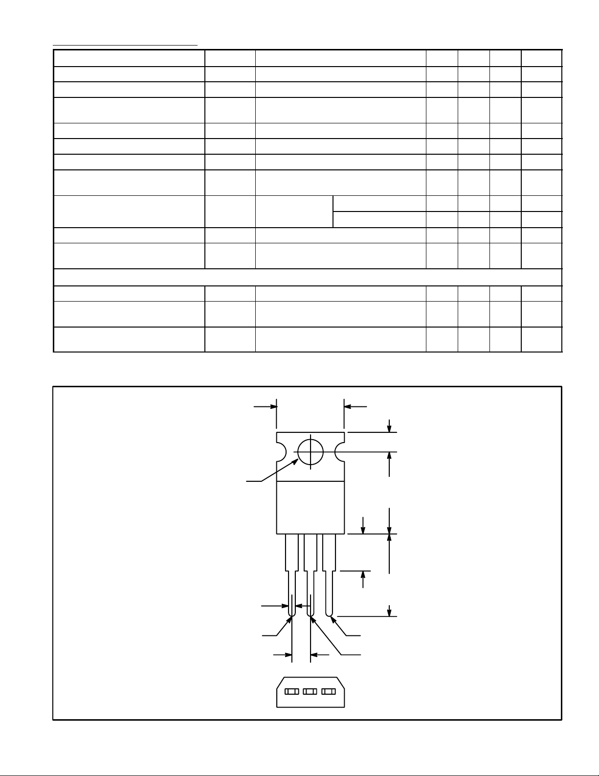
.420 (10.67)
Max
.110 (2.79)
GND
.147
(3.75)
Dia
Max
.070 (1.78) Max
V
.250 (6.35)
IN
Max
V
.500
(12.7)
Max
.500
(12.7)
Min
OUT
.100 (2.54)
GND
 Loading...