

NTE1930
Integrated Circuit
Positive Adjustable Voltage Regulator,
5V to 37V, 25mA
Description:
The NTE1928 is an adjustable positive voltage regulator in an 8–Lead DIP type package that features
fast response to both load and line transients, freedom from oscillations with varying resistive and
reactive loads, and the ability to start reliabity on any load within rating. This device also contains a
biasing circuitry that removes any minimum load current requirement and at the same time reduces
standby current drain, permitting higher voltage operation.
Features:
D Output Voltage Adjustable from 5V to 37V
D Output Currents in Excess of 10A Possible by Adding External Transistors
D Load Regulation Better than 0.1%, Full Load with Current Limiting
D DC Line Regulation Guaranteed at 0.03%/V
D Ripple Rejection on 0.01%V
Absolute Maximum Ratings:
Input Voltage 40V. . . . . . . . . . . . . . . . . . . . . . . . . . . . . . . . . . . . . . . . . . . . . . . . . . . . . . . . . . . . . . . . . . . . . .
Input–Output Differential 40V. . . . . . . . . . . . . . . . . . . . . . . . . . . . . . . . . . . . . . . . . . . . . . . . . . . . . . . . . . . .
Power Dissipation (Note 1), P
Operating Temperature Range, T
Storage Temperature Range, T
D
opr
stg
Lead Temperature (During Soldering, 10 seconds), T
Typical Thermal Resistance, Junction–to–Ambient, R
–65° to +150°C. . . . . . . . . . . . . . . . . . . . . . . . . . . . . . . . . . . . . . . . . .
L
thJA
400mW. . . . . . . . . . . . . . . . . . . . . . . . . . . . . . . . . . . . . . . . . . . . . . . . . . . .
–0° to +70°C. . . . . . . . . . . . . . . . . . . . . . . . . . . . . . . . . . . . . . . . . .
+260°C. . . . . . . . . . . . . . . . . . . . . . . . . . . . . . .
140°C/W. . . . . . . . . . . . . . . . . . . . . . . . . . .
Note 1. The maximum junction temperature of the NTE1930 is 100°C. For operation at elevated
temperatures, this device must be derated based on a thermal resistance of 138°C/W junc-
tion to ambient, or 25°C/W junction to case.
Electrical Characteristics (Note 2)
Parameter Conditions Min Typ Max Units
Input Voltage Range 9 – 40 V
Output Voltage Range 5 – 37 V
Input–Output Voltage Differential 3.0 – 30 V
Load Regulation
Line Regulation
Feedback Sense Voltage 1.60 1.72 1.80 V
Standby Current Drain VIN = 30V, TA = 25°C – – 2.5 mA
Current Limit Sense Voltage TA = 25°C, RSC = 10Ω,
0 ≤ IO ≤ 25mA, RSC = 0Ω, TA = 25°C, Note 3 – – 0.2 %
0 ≤ IO ≤ 25mA, RSC = 0Ω, TA = 70°C, Note 3 – – 0.5 %
0 ≤ IO ≤ 25mA, RSC = 0Ω, TA = 0°C, Note 3 – – 0.5 %
TA = 25°C – – 0.03 %/V
0°C ≤ TA ≤ 70°C – – 0.1 %/V
– 300 – mV
V
= 0V, (Note 4)
OUT
Note 2. Unless otherwise specified, these specifications apply for temperatures within the operating
temperature range, for input and output voltages within the range given, and for a divider
impedance seen by the feedback terminal of 2kΩ. Load and line regulation specifications
are for a constant junction temperature. Temperature drift effects must be taken into account
separately when the unit is operating under conditions of high dissipation.
Note 3. The output currents given, as well as the load regulation, can be increased by the addition
of external transistors. The improvement factor will be roughly equal to the composite current gain of the added transistors.
Note 4. With no external pass transistor.
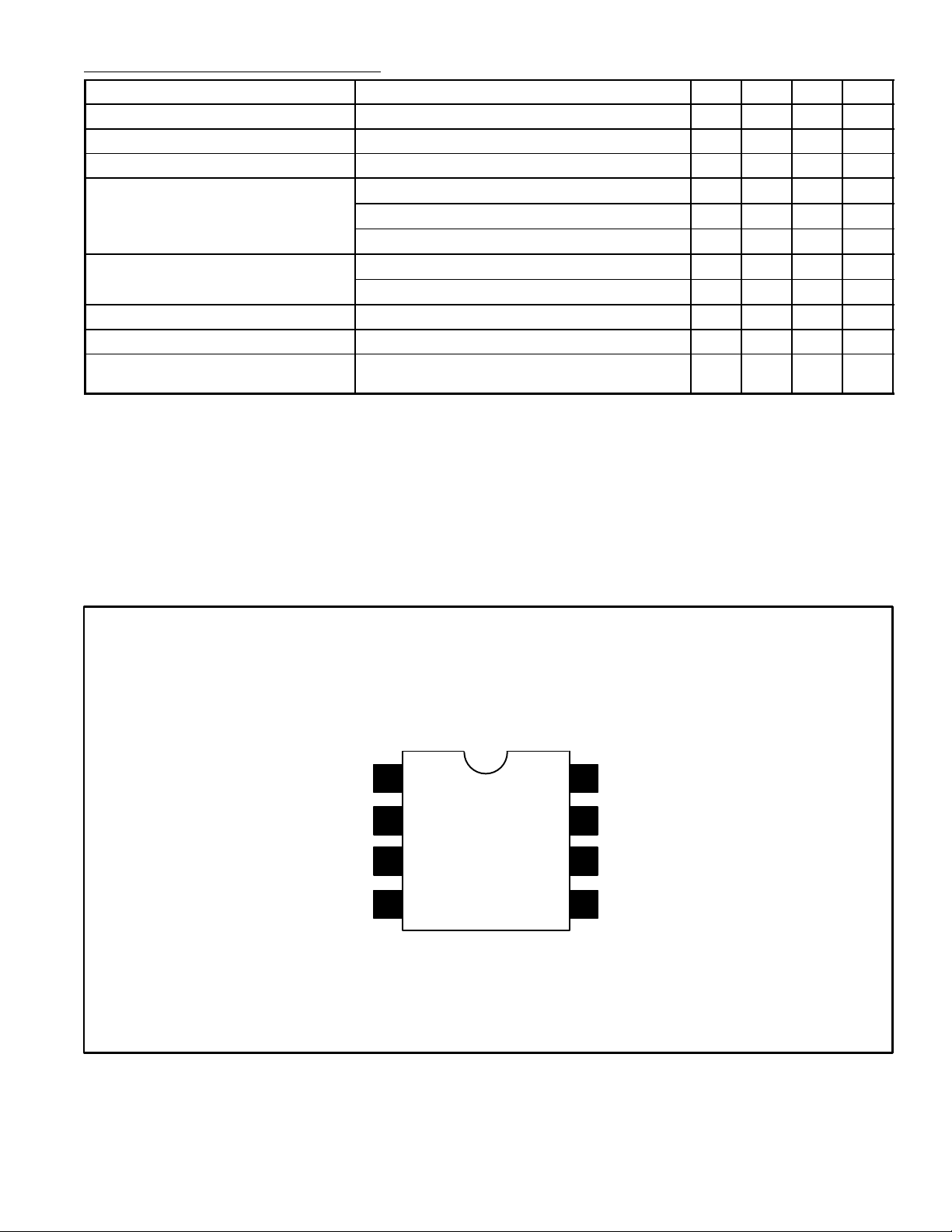
Current Limit
Booster Output
Unregulated Input
GND
Pin Connection Diagram
1
2
3
4
8
Regulated Output
7
Compensation
6
Feedback
5
Reference Bypass
 Loading...