

NTE NTE1919 Datasheet

NTE1919
Integrated Circuit
Negative 3 Terminal Voltage Regulator,
–15V, 1.5A
Description:
The NTE1919 is a 3 terminal fixed n egative v oltage r egulator i n a TO3 type package designed for use
in applications r equiring a w ell regulated positive o utput v oltage. Outstanding f eatures i nclude f ull power
usage up to 1.5A of load current, internal current limiting, thermal shutdown, and safe area protection
on the chip, providing protection of the series pass Darlington, under most operating conditions.
Hermetically sealed steel packages are utilized for high reliability and low thermal resistance. A low–
noise temperature stable band–gap reference is the key design factor insuring excellent temperature
regulation of the N TE1919. This coupled to a very l ow o utput i mpedance i nsures s uperior l oad r egulation.
Features:
D Guaranteed Input–Output Differential: VIN – VO = –2.1V
D Low Noise, Band Gap Reference
D Remote Sense Capability
D Sample Power Cycled Burn–In
D Guaranteed Thermal Resistance Junction–to–Case: R
= 3°C/W
thJC
Absolute Maximum Ratings:
Input Voltage (Note 1), V
Power Dissipation, P
Derate Above T
Operating Junction Temperature Range, T
Storage Temperature Range, T
IN
D
= 105°C 333mW/°C. . . . . . . . . . . . . . . . . . . . . . . . . . . . . . . . . . . . . . . . . . . . . . .
C
J
stg
Lead Temperature (During Soldering, 60sec Max), T
Thermal Resistance, Junction–to–Case, R
thJC
Note 1. Short circuit protection is only assured to V
voltages approaching VINmax, r egulator m ay r equire t he r emoval o f t he i nput v oltage t o r estart.
–40V. . . . . . . . . . . . . . . . . . . . . . . . . . . . . . . . . . . . . . . . . . . . . . . . . . . . . . . . .
Internally Limited. . . . . . . . . . . . . . . . . . . . . . . . . . . . . . . . . . . . . . . . . . . . . . . . . .
–55° to +150°C. . . . . . . . . . . . . . . . . . . . . . . . . . . . . . . . . .
–65° to +150°C. . . . . . . . . . . . . . . . . . . . . . . . . . . . . . . . . . . . . . . . . .
L
+300°C. . . . . . . . . . . . . . . . . . . . . . . . . . . . . . . .
3°C/W. . . . . . . . . . . . . . . . . . . . . . . . . . . . . . . . . . . . . . .
max. In case of short circuit, with input–output
IN
Electrical Characteristics: (TJ = +25°C unless otherwise specified)
Parameter Symbol Test Conditions Min Typ Max Unit
Output Voltage V
Input–Output Differential VIN–VOIO = 1A, TJ = 0 to +125°C –2.1 – – V
Line Regulation Reg
Load Regulation Reg
Quiescent Current I
Quiescent Current Line I
Quiescent Current Load I
Current Limit I
Temperature Coefficient T
Output Noise Voltage V
Ripple Attenuation R
Q(Line)VIN
Q(Load)VIN
LIM
VIN = –20V to –25V, IO = 10mA to 1A, Note 2 14.05 15.0 16.05 V
O
LineVIN
LoadVIN
Q
C
N
A
= –20V to –25V, IO = 1A, Note 2 – – 2.0 % V
= –20V, IO = 10mA to 1.5A, Note 2 – – 0.6 % V
VIN = –20V, IO = 10mA – – 10 mA
= –20V to –30V, IO = 10mA – – 1.3 mA
= –20V, IO = 10mA to 1.5A – – 0.75 mA
VIN = –20V, Note 2 – – 3.5 A
VIN = –20V, IO = 100mA, TJ = 0 to +125°C – – 0.03 % VO/°C
VIN = –20V, IO = 100mA. TJ = 0 to +125°C, Note 3 – – 10 µV
VIN = –20V, IO = 1A, TJ = 0 to +125°C, Note 4 54 – – dB
rms
O
O
/V
Note 2. Low duty cycle pulse testing with Kelvin connections required. Die temperature changes
must be accounted for separatly.
Note 3. BW = 10Hz to 100kHz.
Note 4. Ripple attenuation is specified for a 1Vrms, 120Hz, input ripple. Ripple attenuation is mini-
mum of 60dB at 5V output and is 1dB less for each volt increase in the output voltage.
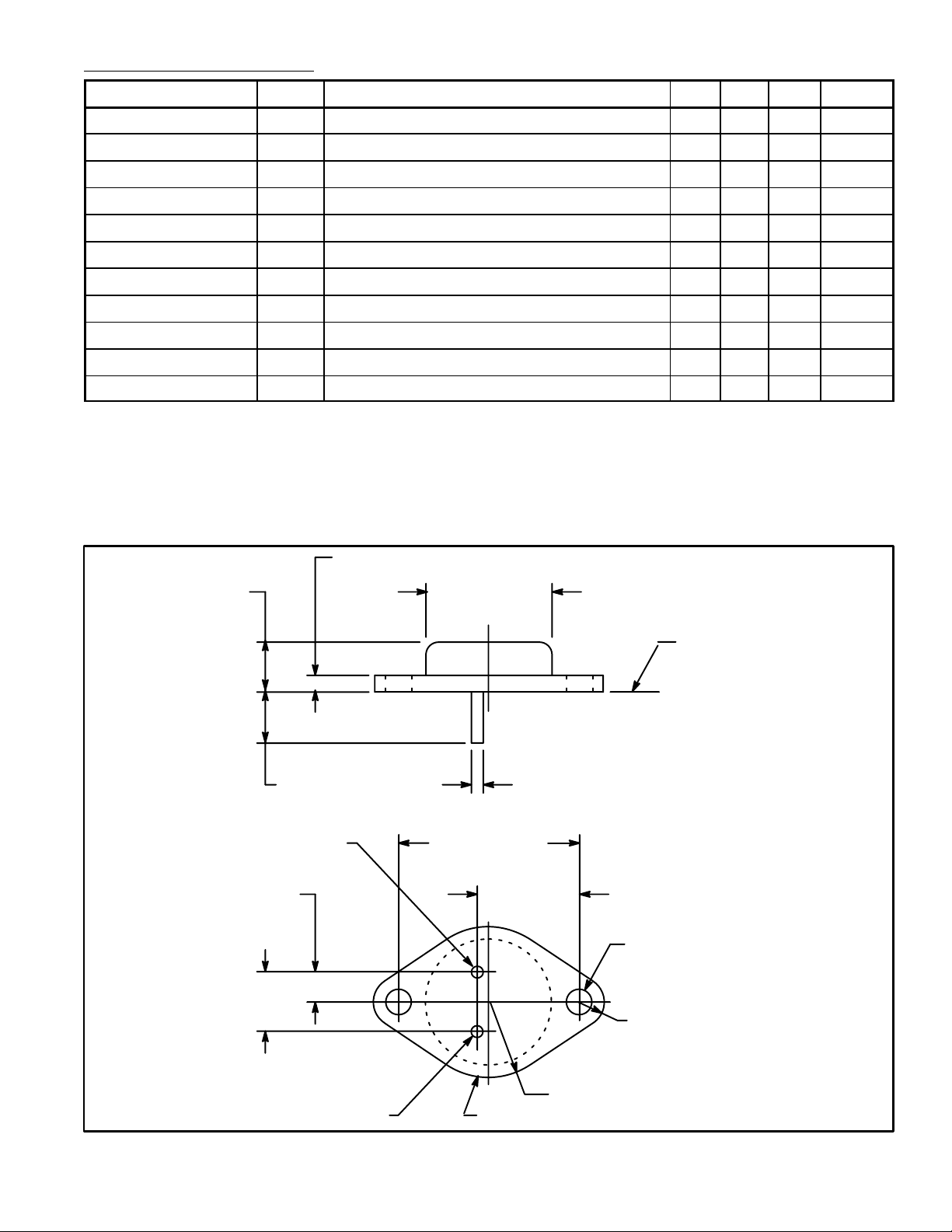
.135 (3.45) Max
.350 (8.89)
.215 (5.45)
.430
(10.92)
V
OUT
.875 (22.2)
Dia Max
Seating
Plane
.040 (1.02).312 (7.93) Min
1.187 (30.16)
.665
(16.9)
.156 (3.96) Dia
(2 Holes)
.188 (4.8) R Max
.525 (13.35) R Max
VIN/CaseGND
 Loading...