

NTE NTE1915 Datasheet

NTE1915
Integrated Circuit
Negative 3 Terminal Voltage Regulator
–12V, 1.5A
Description:
The NTE1915 is a 3 terminal negative regulator in a TO3 type package with a fixed output voltage
of –12V and up to 1.5A load current capability. Where other voltages are required, the NTE1911 provides an output voltage range of –1.2V to –37V.
This device needs only one external component – a compensation capacitor at the output, making
it easy to apply. Worst case guarantees on output voltage deviation due to any combination of line,
load, or temperature variation assure satisfactory system operation.
Exceptional ef fort has been made to make the NTE1915 immune to onerload conditions. This regulator has current limiting which is independent of temperature, combined with thermal overload protection. Internal current limiting protects against momentary faults while thermal shutdown prevents
junction temperatures from exceeding safe limits during prolonged overloads.
Although primarily intended for fixed output voltage applications, the NTE1915 may be programmed
for higher output voltages with a single resistive divider. The low quiescent drain current of the device
allows this technique to be used woth good regulation.
Features:
D Preset Output Voltage Error Less Than ±3%
D Preset Current Limit
D Internal Thermal Shutdown
D Operates with Input–Output Voltage Differential Down to 1V
D Excellent Ripple Rejection
D Low Temperature Drift
D Easily Adjustable to Higher Output Voltage
Absolute Maximum Ratings:
Input Voltage, V
Input–Output Voltage Differential, V
Power Dissipation, P
Junction Temperature Range, T
Storage Temperature Range, T
Lead Temperature (During Soldering, 10sec), T
Thermal Resistance, Junction–to–Case, R
Thermal Resistance, Junction–to–Ambient, R
IN
I–VO
D
J
stg
L
thJC
thJA
–35V. . . . . . . . . . . . . . . . . . . . . . . . . . . . . . . . . . . . . . . . . . . . . . . . . . . . . . . . . . . . . . . . .
30V. . . . . . . . . . . . . . . . . . . . . . . . . . . . . . . . . . . . . . . . . . . . . . .
Internally Limited. . . . . . . . . . . . . . . . . . . . . . . . . . . . . . . . . . . . . . . . . . . . . . . . . .
0° to +125°C. . . . . . . . . . . . . . . . . . . . . . . . . . . . . . . . . . . . . . . . . . . . .
–65° to +150°C. . . . . . . . . . . . . . . . . . . . . . . . . . . . . . . . . . . . . . . . . .
+300°C. . . . . . . . . . . . . . . . . . . . . . . . . . . . . . . . . . . .
3°C/W. . . . . . . . . . . . . . . . . . . . . . . . . . . . . . . . . . . . . . .
35°C/W. . . . . . . . . . . . . . . . . . . . . . . . . . . . . . . . . . .
Electrical Characteristics: (0° ≤ TJ ≤ +125°C, IO = 1A, PD = 20W unless otherwise specified)
Parameter Symbol Test Conditions Min Typ Max Unit
Output Voltage V
Input Voltage V
Line Regulation Reg
Ripple Rejection RR f = 120Hz 56 80 – dB
Load Regulation Reg
Quiesecnt Current I
Quiescent Current Change ∆I
Output Noise Voltage V
Long Term Stability – 12 120 mV
OUT
TJ = +25°C, VIN = 17V, I
14.5V ≤ VIN ≤ V
IN
LINETJ
LOADTJ
B
B
n
= +25°C, I
= +25°C, VIN = 17V, 5mA ≤ I
V
≤ VIN ≤ V
MIN
TJ = +25°C, V
5mA ≤ I
TA = +25°C, CL = 1µF, IL = 5mA, VIN = 17V,
10Hz ≤ f ≤ 100kHz
LOAD
LOAD
MAX
MIN
≤ I
MAX
O
LOAD
, 5mA ≤ I
= 5mA, V
≤ VIN ≤ V
MIN
MAX
= 5mA –12.4 –12.0 –11.6 V
≤ IO, P ≤ P
LOAD
≤ VIN ≤ V
LOAD
MAX
≤ IO, Note 1 – 30 80 mV
–12.6 –12.0 –11.4 V
D
–32 – –14 V
– 4 20 mV
– 2 4 mA
– 0.1 0.4 mA
– 0.1 0.4 mA
– 400 – µV
Note 1. Regulation is measured at constant junction temperature. Changes in output voltage due
to heating effects must be taken into account separately. To ensure constant junction temperature, low duty cycle, pulse testing is used. The NTE1915 does have low thermal feedback, improving line and load regulation. On all other tests, even though power dissipation
is internally limited, electrical specifications apply only up to P
.
D
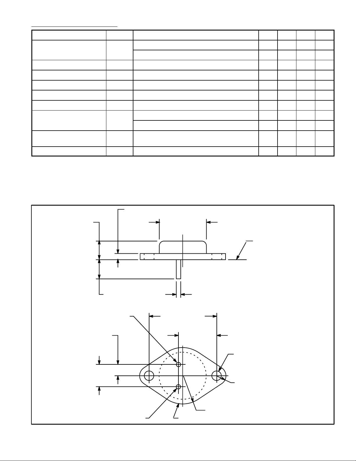
.135 (3.45) Max
.350 (8.89)
.215 (5.45)
.430
(10.92)
V
OUT
.875 (22.2)
Dia Max
Seating
Plane
.040 (1.02).312 (7.93) Min
1.187 (30.16)
.665
(16.9)
.156 (3.96) Dia
(2 Holes)
.188 (4.8) R Max
.525 (13.35) R Max
VIN/CaseGND
 Loading...