

NTE NTE1914 Datasheet
NTE1914
3 Terminal Positive Voltage Regulator
12V, 1A
Description:
The NTE1914 is a positive 3–terminal voltage regulator in a TO3 type package suitable for numerous
applications requiring up to 1A. One of these is local on card regulation, eliminating the distribution
problems associated with single point regulation. Other applications include; logic systems, instrumentation, HiFi, and other solid state lectronic equipment. Although designed primarily as a fixed voltage regulator, the NTE1914 can be used with external components to obtain adjustable voltages and
currents.
Features:
D Output Current in Excess of 1A
D Internal Thermal Overload Protection
D No External Components Required
D Output Transistor Safe Area Protection
D Internal Short Circuit Current Limit
Absolute Maximum Ratings:
Input Voltage , V
Power Dissipation (Note 1), P
Maximum Junction Temperature, T
Operating Junction Temperature Range, T
Storage Temperature Range, T
IN
D
J
A
stg
Lead Temperature (During Soldering, 10 sec), T
Internally Limited. . . . . . . . . . . . . . . . . . . . . . . . . . . . . . . . . . . . . . . . . . .
0° to +70°C. . . . . . . . . . . . . . . . . . . . . . . . . . . . . . . . . . . . .
–65° to +150°C. . . . . . . . . . . . . . . . . . . . . . . . . . . . . . . . . . . . . . . . . .
L
35V. . . . . . . . . . . . . . . . . . . . . . . . . . . . . . . . . . . . . . . . . . . . . . . . . . . . . . . . . . . . . . . . . .
+150°C. . . . . . . . . . . . . . . . . . . . . . . . . . . . . . . . . . . . . . . . . . . . . . .
+300°C. . . . . . . . . . . . . . . . . . . . . . . . . . . . . . . . . . . .
Note 1. Thermal resistance is typically +4°C/W junction–to–case and +35°C/W junction–to–ambient.
Electrical Characteristics:
(0° ≤ TJ ≤ +125°C, VO = 12V, VIN = 19V, Note 2 unless otherwise
specified)
Parameter Symbol Test Conditions Min Typ Max Unit
Output Voltage V
TA = +25°C, 5mA ≤ IO ≤ 1A 11.5 12.0 12.5 V
O
5mA ≤ IO ≤ 1A, 14.5V ≤ VIN ≤ 27V, P ≤ 15W 11.4 12.0 12.6 V
Note 2. All characteristics are measured with a 0.22µF capacitor across the input and a 0 . 1µF capac-
itor across the output. All characteristics except noise voltage and ripple rejection ratio are
measured using pulse tecniques (t
≤ 10ms, duty cycle ≤ 5%). Output voltage changes due
w
to changes in internal temperature must be taken into account separately.
Electrical Characteristics (Cont’d): (0° ≤ TJ ≤ +125°C, VO = 12V, VIN = 19V, Note 2 unless
otherwise specified)
Parameter Symbol Test Conditions Min Typ Max Unit
Line Regulation Reg
line
TJ = +25°C
14.5V ≤ VIN ≤ 30V, IO = 500mA – 4 120 mV
14.6V ≤ VIN ≤ 27V, IO ≤ 1A – – 120 mV
15V ≤ VIN ≤ 27V, IO = 500mA – – 120 mV
16V ≤ VIN ≤ 22V, IO ≤ 1A – – 60 mV
Load Regulation Reg
load
TJ = +25°C
5mA ≤ IO ≤ 1.5A – 12 120 mV
250mA ≤ IO ≤ 750mA – – 60 mV
5mA ≤ IO ≤ 1A – – 120 mV
Quiescent Current I
TJ = +25°C, IO ≤ 1A – – 8.0 mA
Q
IO ≤ 1A – – 8.5 mA
Quiescent Current Change I
5mA ≤ IO ≤ 1A – – 0.5 mA
Q
TA = +25°C, IO ≤ 1A, 14.8V ≤ VIN ≤ 27V – – 1.0 mA
IO ≤ 500mA, 14.5V ≤ VIN ≤ 30V – – 0.5 mA
Output Noise Voltage V
TA = +25°C, f = 10Hz to 100kHz – 75 – µV
n
Ripple Rejection Ratio RR TA = +25°C, 15V ≤ VIN ≤ 25V, f = 120Hz, IO ≤ 1A 55 72 – dB
15V ≤ VIN ≤ 25V, f = 120Hz, IO ≤ 500mA 55 – – dB
Dropout Voltage TJ = +25°C, IO = 1A – 2.0 – V
Peak Output Current IOmax TJ = +25°C – 2.4 – A
Average Temperature
IO = 5mA – 1.5 – mV/°C
Coefficient of Output
Voltage
Note 2. All characteristics are measured with a 0.22µF capacitor across the input and a 0 . 1µF capac-
itor across the output. All characteristics except noise voltage and ripple rejection ratio are
measured using pulse tecniques (t
≤ 10ms, duty cycle ≤ 5%). Output voltage changes due
w
to changes in internal temperature must be taken into account separately.
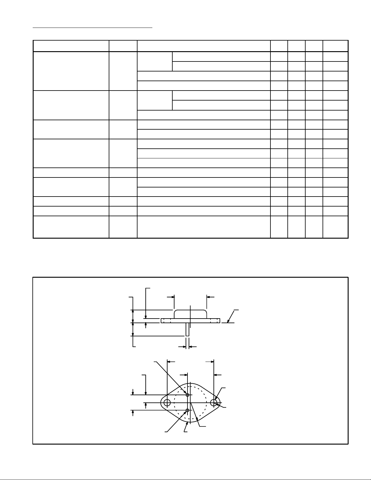
.135 (3.45) Max
.350 (8.89)
.215 (5.45)
.430
(10.92)
V
OUT
V
IN
.875 (22.2)
Dia Max
Seating Plane
.040 (1.02).312 (7.93) Min
1.187 (30.16)
.665
(16.9)
.188 (4.8) R Max
.156 (3.96) Dia
(2 Holes)
.525 (13.35) R Max
Common/Case
 Loading...