

NTE NTE1913 Datasheet

NTE1913
Integrated Circuit
Negative 3 Terminal Voltage Regulator,
–5V, 1.5A
Description:
The NTE1913 i s a 3 t erminal fixed negative voltage regulator in a TO3 type package suitable for numerous applications r equiring u p t o 1 .5A. This device employs i nternal c urrent l imiting s afe a rea p rotection
and thermal shutdown for protection against virtually all overload conditions.
Low ground pin current allows output voltage to be easily boosted above the preset value with a resister divider. The low quiescent current rain of the NTE1913 with a specified maximum change with line
and load ensures good regulation in the voltages boosted mode.
Features:
D Thermal, Short Circuit, and Safe Area Protection
D High Ripple Rejection
D 4% Preset Output Voltage
Absolute Maximum Ratings:
Input Voltage, V
Input–Output Differential, V
Power Dissipation (Note 1), P
Operating Junction Temperature Range, T
Storage Temperature Range, T
Lead Temperature (During Soldering, 10sec Max), T
IN
IN–VO
D
J
stg
Internally Limited. . . . . . . . . . . . . . . . . . . . . . . . . . . . . . . . . . . . . . . . . . .
0° to +125°C. . . . . . . . . . . . . . . . . . . . . . . . . . . . . . . . . . . .
–65° to +150°C. . . . . . . . . . . . . . . . . . . . . . . . . . . . . . . . . . . . . . . . . .
L
–35V. . . . . . . . . . . . . . . . . . . . . . . . . . . . . . . . . . . . . . . . . . . . . . . . . . . . . . . . . . . . . . . . .
25V. . . . . . . . . . . . . . . . . . . . . . . . . . . . . . . . . . . . . . . . . . . . . . . . . . . . .
+230°C. . . . . . . . . . . . . . . . . . . . . . . . . . . . . . . .
Note 1. Thermal resistance, junction–to–ambient is +50°C/W (no heat sink) and +5°C/W (infinite
heat sink).
Electrical Characteristics: (0°≤ TJ ≤ +125°C, PD ≤ 1.5W, VO = –5V, VIN = –10V, IO = 500mA,
C
= 2.2µF, C
IN
Parameter Symbol Test Conditions Min Typ Max Unit
= 1µF unless otherwise specified)
OUT
Output Voltage V
Line Regulation Reg
Load Regulation Reg
Quiescent Current I
Quiescent Current Line I
Quiescent Current Load I
Output Noise Voltage V
Ripple Rejection RR –18V ≤ VIN ≤ –8V, f = 120Hz 54 66 – dB
Dropout Voltage TJ = +25°C, IO = 1A – 1.1 – V
peak Output Current IOmax TJ = +25°C – 2.2 – A
Temperature Coefficient 0° ≤ TJ ≤ +100°C, IO = 5mA – 0.4 – mV/°C
Q(Line)
Q(Load)
TJ = +25°C –4.8 –5.0 –5.2 V
O
–20V ≤ VIN ≤ –7.5V, 5mA ≤ IO ≤ 1A, P ≤ 15W –7.45 –5.00 –5.25 V
LineTJ
LoadTJ
Q
N
= +25°C, –25V ≤ VIN ≤ –7V, Note 2 – 8 50 mV
TJ = +25°C, –12V ≤ VIN ≤ –8V, Note 2 – 2 15 mV
= +25°C, 5mA ≤ IO ≤ 1.5A, Note 2 – 15 100 mV
TJ = +25°C, 250mA ≤ IO ≤ 750A, Note 2 – 5 50 mV
TJ = +25°C – 1 2 mA
–25V ≤ VIN ≤ –7V – – 0.5 mA
5mA ≤ IO ≤ 1.5A – – 0.5 mA
TA = +25°C, f = 10Hz to 100Hz – 125 – µV
Note 2. Regulation is measured at a constant temperature by pulse testing with a low duty cycle.
Change in output voltage due to heating effects must be taken into account.
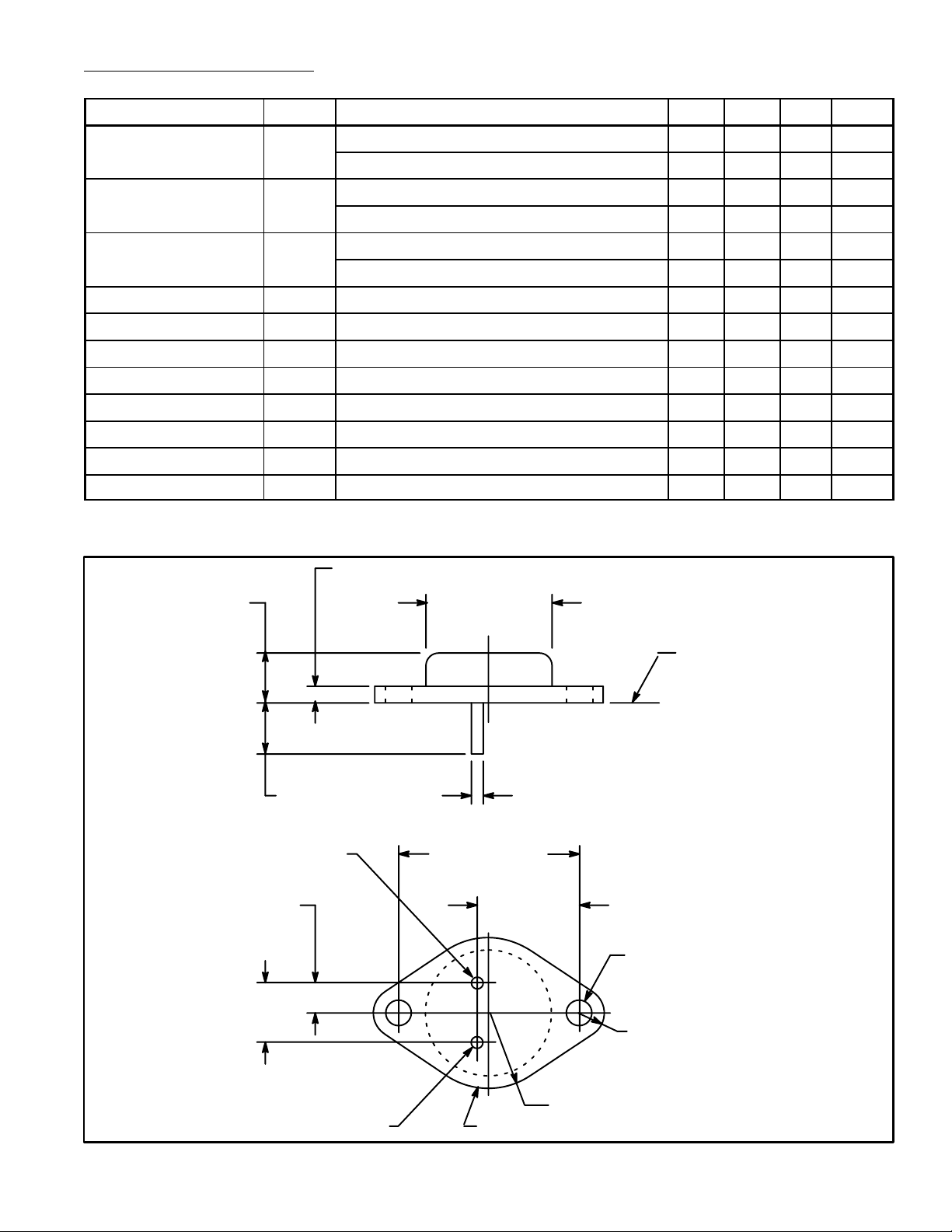
.135 (3.45) Max
.350 (8.89)
.215 (5.45)
.430
(10.92)
V
OUT
.875 (22.2)
Dia Max
Seating
Plane
.040 (1.02).312 (7.93) Min
1.187 (30.16)
.665
(16.9)
.156 (3.96) Dia
(2 Holes)
.188 (4.8) R Max
.525 (13.35) R Max
VIN/CaseGND
 Loading...