

NTE NTE1902 Datasheet
NTE1902
Integrated Circuit
3 Terminal Positive Voltage Regulator
9V, 100mA
Features:
D Output Current up to 100mA
D No External Components
D Internal Thermal Overload Protection
D Internal Short–Circuit Current Limiting
D Output Voltage Tolerances of ±5% over the Temperature Range
Absolute Maximum Ratings:
Input Voltage, V
Internal Power Dissipation, P
Operating Junction Temperature Range, T
Storage Temperature Range, T
Lead Temperature (During Soldering, 10sec), T
IN
D
J
stg
L
35V. . . . . . . . . . . . . . . . . . . . . . . . . . . . . . . . . . . . . . . . . . . . . . . . . . . . . . . . . . . . . . . . . .
Internally Limited. . . . . . . . . . . . . . . . . . . . . . . . . . . . . . . . . . . . . . . . . . .
0° to +125°C. . . . . . . . . . . . . . . . . . . . . . . . . . . . . . . . . . . .
–55° to +150°C. . . . . . . . . . . . . . . . . . . . . . . . . . . . . . . . . . . . . . . . . .
+260°C. . . . . . . . . . . . . . . . . . . . . . . . . . . . . . . . . . . .
Electrical Characteristics:
Parameter Symbol Test Conditions Min Typ Max Unit
Output Voltage V
Line Regulation Reg
Load Regulation Reg
Quiescent Current I
Quiescent Current Change I
Output Noise Voltage V
Temperature Coefficient of V
Ripple Rejection RR TJ = +25°C, 15V ≤ VIN ≤ 25V, f = 120Hz 38 44 – dB
Dropout Voltage V
Peak Output/Short Circuit Current Ipk/I
OUT
(V
C
= 9V, VIN = 15V, 0° ≤ TJ ≤ +125°C, IO = 40mA, CIN = 0.33µF,
OUT
= 0.1µF, Note 1 unless otherwise specified)
OUT
TJ = +25°C 8.64 9.00 9.36 V
O
1mA ≤ IO ≤ 70mA, 11.5V ≤ VIN ≤ 24V 8.55 9.00 9.45 V
LineTJ
LoadTJ
B
B
N
DO
OSTJ
= +25°C 11.5V ≤ VIN ≤ 24V – 90 200 mV
13V ≤ VIN ≤ 24V – 100 150 mV
= +25°C 1mA ≤ IO ≤ 100mA – 20 90 mV
1mA ≤ IO ≤ 40mA – 10 45 mV
With line, 11.5V ≤ VIN ≤ 24V – – 1.5 mA
With load, 1mA ≤ IO ≤ 40mA – – 0.1 mA
TA = +25°C, f = 10Hz to 10kHz – 70 – µV
I
= 5mA – –0.9 – mV/°C
OUT
TJ = +25°C – 1.4 – V
= +25°C – 140 – mA
– 2.1 5.5 mA
Note 1. The maximum steady state usable output current and input voltage ar very dependent on
the heat sink and/or lead length of the package. The data above represents pulse test conditions with junction temperatures as indicated at the initiation of the test.
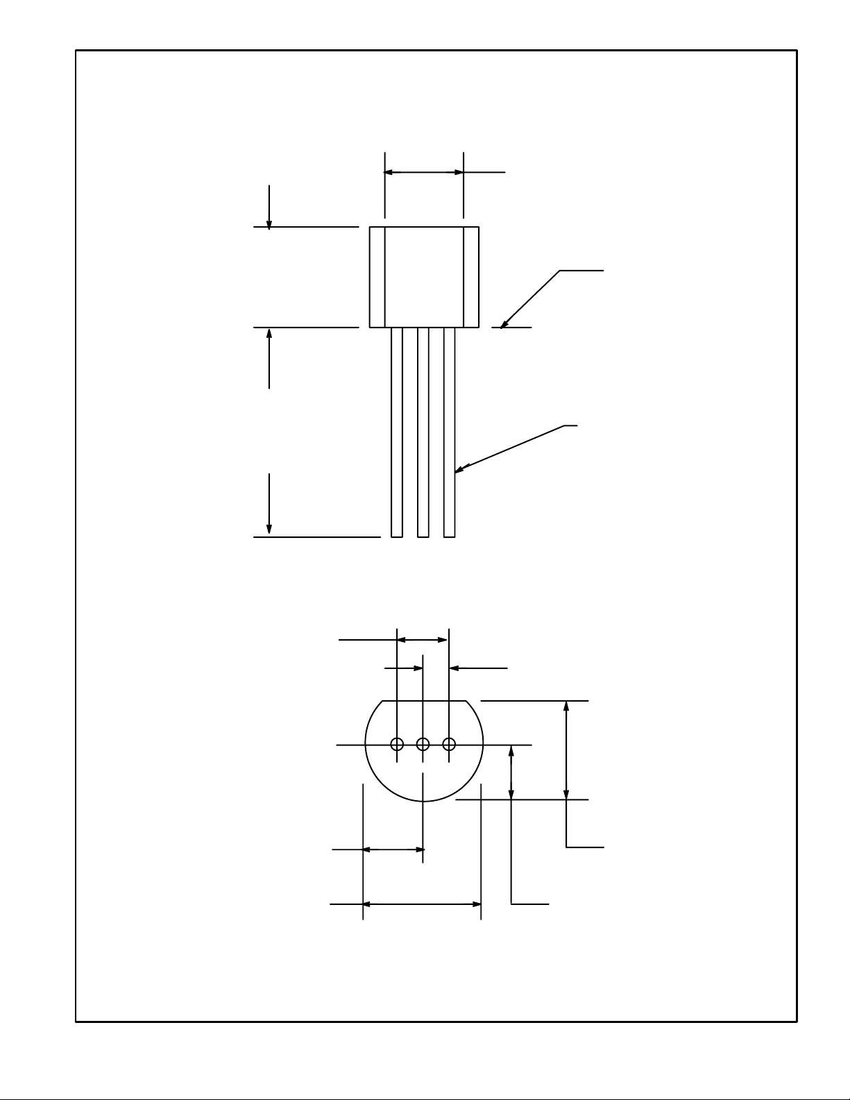
.135 (3.45) Min
.210
(5.33)
Max
.500
(12.7)
Min
.100 (2.54)
V
OUT
GND
V
Seating
Plane
.021 (.445) Dia Max
IN
.105 (2.67) Max
.205 (5.2) Max
.050 (1.27)
.165 (4.2) Max
.105 (2.67) Max
 Loading...