

NTE NTE1846 Datasheet
NTE1846
Integrated Circuit
NTSC System Single–Chip Color TV Signal Processor
Description:
The NTE1846 is an integrated circuit in a 52–Lead DIP type package designed for use as a color TV
signal processor. This device contains signal processing functions for video IF, sound IF, video, color,
deflection signals, on a single chip.
Combined with a tuner and a simple output stage of discreet transistors, the NTE1846 enables more
rationalized designs for color TV sets.
Features:
D Large Integration Enables Rationalization and High Reliability of Equipment and Low Power
Consumption.
D A Direct Output Pin for Sound FM Detector is Provided, Applicable to Sound Multiplexing.
D The Most Appropriate Constants can be Set by the Synchronization Separation Input Pins for
Horizontal and Vertical Deflection.
D No Horizontal Free Run Frequency Adjustments.
D Capable of AFT Defeat, Sound Muting
D DC Volume Controls Picture Quality, Contrast, Luminance, Color Saturation, Tint, and Volume.
Application:
NTSC System Color Television Set
Absolute Maximum Ratings
Supply Voltage, V
Power Dissipation, P
Operating Temperature Range, T
Storage Temperature Range, T
Recommended Operating Conditions:
Supply Voltage 9V. . . . . . . . . . . . . . . . . . . . . . . . . . . . . . . . . . . . . . . . . . . . . . . . . . . . . . . . . . . . . . . . . . . . .
Horizontal Supply Current 14mA. . . . . . . . . . . . . . . . . . . . . . . . . . . . . . . . . . . . . . . . . . . . . . . . . . . . . . . . .
Operating Supply Voltage 8.5V to 9.5V. . . . . . . . . . . . . . . . . . . . . . . . . . . . . . . . . . . . . . . . . . . . . . . . . . .
Operating Horizontal Supply Currents 12mA to 16mA. . . . . . . . . . . . . . . . . . . . . . . . . . . . . . . . . . . . . .
CC
D
: (TA = +25°C, unless otherwise specified)
opr
stg
1.4W. . . . . . . . . . . . . . . . . . . . . . . . . . . . . . . . . . . . . . . . . . . . . . . . . . . . . . . . . . . . .
–20° to +65°C. . . . . . . . . . . . . . . . . . . . . . . . . . . . . . . . . . . . . . . . .
–40° to +125°C. . . . . . . . . . . . . . . . . . . . . . . . . . . . . . . . . . . . . . . . . .
11V. . . . . . . . . . . . . . . . . . . . . . . . . . . . . . . . . . . . . . . . . . . . . . . . . . . . . . . . . . . . . . . .
Pin Connection Diagram
Electronic Attenuator Control
FM Demodulator Coil
De–Emphasis, Sound Direct I/O
Audio Driver Output
Audio Negative Feedback, Bypass
IF AGC Filter
RF AGC Control
VIF, SIF Power Supply
Horizontal Power Supply
AFC Filter
AFC Flyback Pulse Inpu
32f
OSC
X–Ray Protector Signal Input
Sawtooth Wave Generator Capacitor
Rated Current Pull–In
Vertical AC/DC Feedback Input
VCD Power Supply
Horizontal Pre–Drive Output
H
Vertical Output
Tint Control
Video Output
1
2
3
4
5
6
7
8GND
9VIF Input 44
10VIF Input
11
12 41
13
14 39
15 38
C
16
17Vertical Synchronizing Signal
18Vertical OSC
19
20
21
22
23
24 29
25 28
26 27
52
RF AGC Output
Video Detector Output
51
50
AFT Output
Brightness Control
49
48 SIF Input
47
AFT Coil
Video Detector Coil
46
Video Detector Coil
45
Vertical Synchronization Separation Input
43
Synchronizing Output
Horizontal Synchronization Separation Input
42
Pedestal Holding
40
Video Input 1
Video Input 2
Contrast Control
37 Video Tone Control
36 Color Signal Input
35
GND
34
ACC Filter
33
Killer Filter
APC Filter
32
3.58MHz OSC
31
30
Color Saturation Control
G – Y Demodulated Output
B – Y Demodulated Output
R – Y Demodulated Output
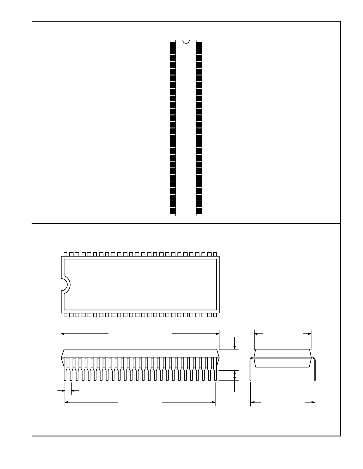
52 27
126
1.813 (46.05) Max
.512 (13.0)
.217
(5.5)
Max
.070 (1.77)
1.750 (44.5)
.118
(3.0)
.600 (15.24)
Min
 Loading...