

NTE NTE1844 Datasheet
NTE1844
Integrated Circuit
Motor Speed Regulator
Description:
The NTE1844 is a monolithic integrated circuit intended for speed regulation of DC motors in record
players, tape, and cassette recorders, conveniently packaged in a 4–Lead SIP type plastic package.
Features:
D High Output/Low Quiescent Currents
D Low Reference Voltage
D Excellent Stability versus Temperature, Parameters
D Excellent Characteristics even at Low Supply Voltages
Absolute Maximum Ratings: (TA = +25°C)
Supply Voltage, V
Circuit Current (t ≤ 5sec), I
Package Dissipation, P
CC
O
D
Operating Temperature Range, T
Storage Temperature Range, T
stg
opr
–20° to +75°C. . . . . . . . . . . . . . . . . . . . . . . . . . . . . . . . . . . . . . . . .
–40° to +150°C. . . . . . . . . . . . . . . . . . . . . . . . . . . . . . . . . . . . . . . . . .
18V. . . . . . . . . . . . . . . . . . . . . . . . . . . . . . . . . . . . . . . . . . . . . . . . . . . . . . . . . . . . . . . .
2A. . . . . . . . . . . . . . . . . . . . . . . . . . . . . . . . . . . . . . . . . . . . . . . . . . . . . . . . . .
1.2W. . . . . . . . . . . . . . . . . . . . . . . . . . . . . . . . . . . . . . . . . . . . . . . . . . . . . . . . . . .
Recommended Operating Condition:
Supply Voltage Range, V
CC
3.5V to 16V. . . . . . . . . . . . . . . . . . . . . . . . . . . . . . . . . . . . . . . . . . . . . . . . . .
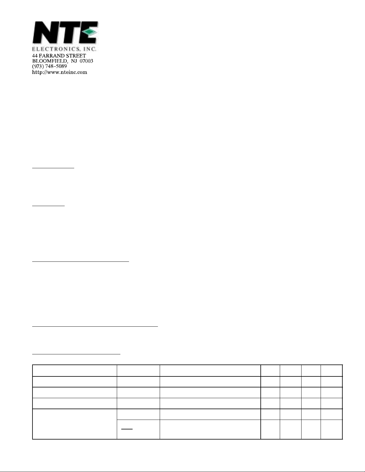
Electrical Characteristics: (TA = +25°C, VCC = 12V, Pulse Test PW ≤ 10ms, Duty Cycle ≤ 2%
unless otherwise specified)
Parameter Symbol Test Conditions Min Typ Max Unit
Reference Voltage V
Quiescent Current I
Reflection Coefficient k RM1 = 44Ω, RM2 = 33Ω 18 20 22
Saturation Voltage V
∆k
k
ref
d
4(sat)
/∆V
I4 = 10mA 1.10 1.27 1.40 V
RM = 180Ω 0.5 0.8 1.2 mA
VCC = 4.2V, RM = 4.4Ω – 1.5 2.0 V
I4 = 100mA, VCC = 6.3V to 16V – 0.4 – %/V
CC
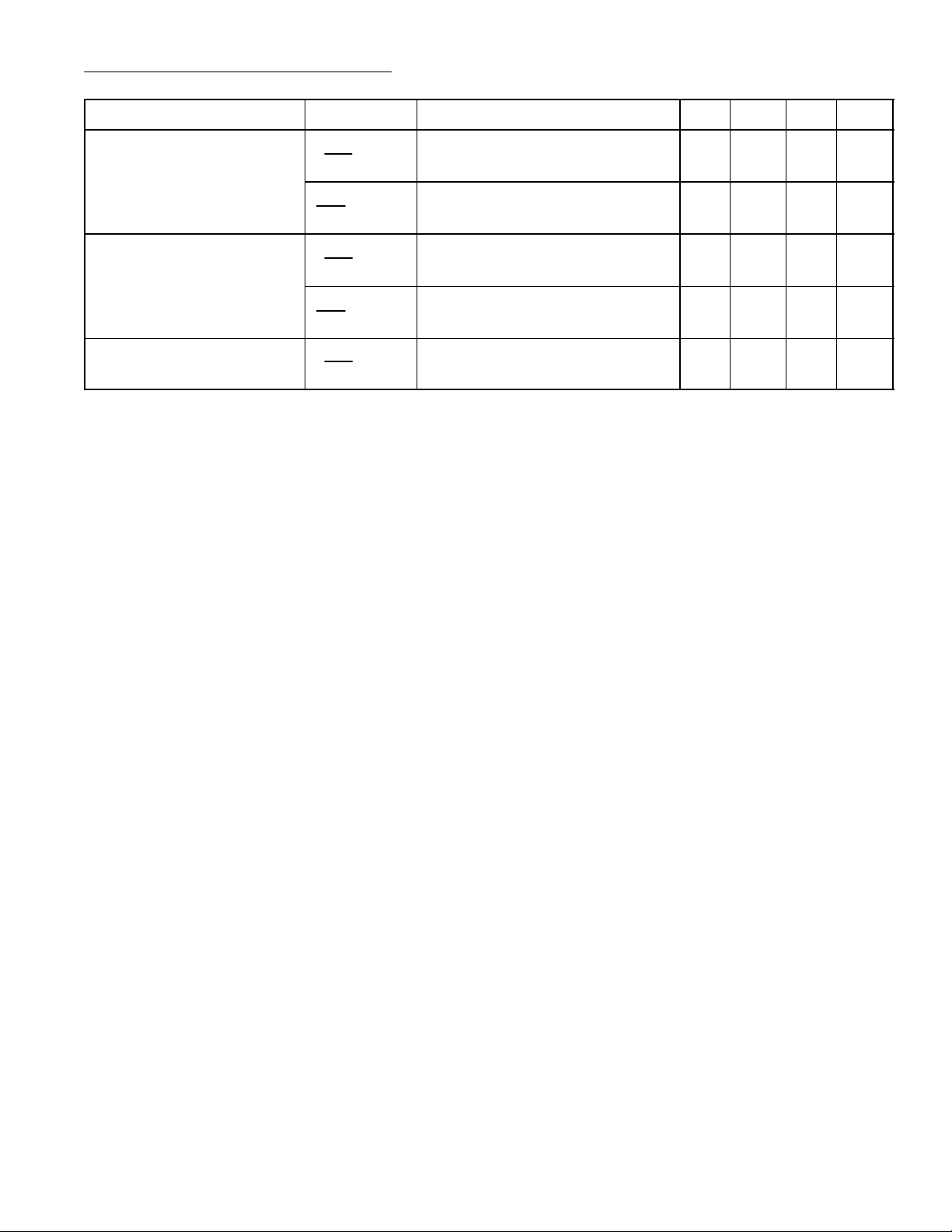
Electrical Characteristics (Cont’d): (TA = +25°C, VCC = 12V, Pulse Test PW ≤ 10ms,
Duty Cycle ≤ 2% unless otherwise specified)
Parameter Symbol Test Conditions Min Typ Max Unit
Line Regulation
Load Regulation
Temperature Coefficient
∆V
V
∆k
∆V
V
∆k
∆V
V
ref
/∆V
ref
/∆I
M
k
ref
/∆I
ref
/∆T
k
ref
/∆T
ref
I4 = 100mA, VCC = 6.3V to 16V – 0.06 – %/V
CC
I4 = 30mA to 200mA – –0.02 – %/m
I4 = 30mA to 200mA – –0.02 – %/m
M
I4 = 100mA, TA = –20° to +75°C – 0.01 – %/°C
A
I4 = 100mA, TA = –20° to +75°C – 0.01 – %/°C
A
Note 1. RM= internal motor resistance
k=I4/I2 where:
I2 and I4 are currents flowing
from VCC thru external resistors
or internal motor resistance to
Pin2 (I2) and Pin4 (I4).
A
A
 Loading...