

NTE NTE1842 Datasheet

NTE1842
Integrated Circuit
FM/AM IF System
Description:
The NTE1842 is a FM/AM IF system IC in a 16–Lead DIP type package designed for portable use.
As compared with conventional ICs, this device is greatly improved in external parts counts and electrical characteristics, espeically tweet and overload distortions.
Features:
D Low Supply Current, AM: 7mA, FM: 10mA (Typ)
D Low Number of External Components
D Excellent Tweet
D Low Overvoltage Distortion
D Tuning Indicator LED Driving Capability: I
D Built–In FM/AM Mode Switch
D Common Output for FM/AM
D Operating Supply Voltage Range: V
CC9opr)
= 10mA (Max)
LAMP
= 3V to 8V
Absolute Maximum Ratings:
Supply Voltage, V
Lamp Current, I
Power Dissipation, P
CC
LAMP
D
(TA = +25°C unless otherwise specified)
Derate Above 25°C 6mW/°C. . . . . . . . . . . . . . . . . . . . . . . . . . . . . . . . . . . . . . . . . . . . . . . . . . . . . . .
Operating Temperature Range, T
Storage Temperature Range, T
DC Characteristics:
Pin1 Voltage (AM Mix Input) V
Pin2 Voltage (AM Mix Bypass) V
Pin3 Voltage (AM OSC) V
Pin4 Voltage (Reg) V
(VCC = 5V, Pin Voltage at No Signal)
Parameter Symbol
opr
stg
8V. . . . . . . . . . . . . . . . . . . . . . . . . . . . . . . . . . . . . . . . . . . . . . . . . . . . . . . . . . . . . . . . .
10mA. . . . . . . . . . . . . . . . . . . . . . . . . . . . . . . . . . . . . . . . . . . . . . . . . . . . . . . . . . . . . .
750mW. . . . . . . . . . . . . . . . . . . . . . . . . . . . . . . . . . . . . . . . . . . . . . . . . . . . . . . . . .
–25°C to +75°C. . . . . . . . . . . . . . . . . . . . . . . . . . . . . . . . . . . . . . .
–55° to +150°C. . . . . . . . . . . . . . . . . . . . . . . . . . . . . . . . . . . . . . . . . .
Typical
AM FM
1
2
3
4
1.5 0 V
1.5 0 V
2.3 2.3 V
2.3 2.3 V
Unit
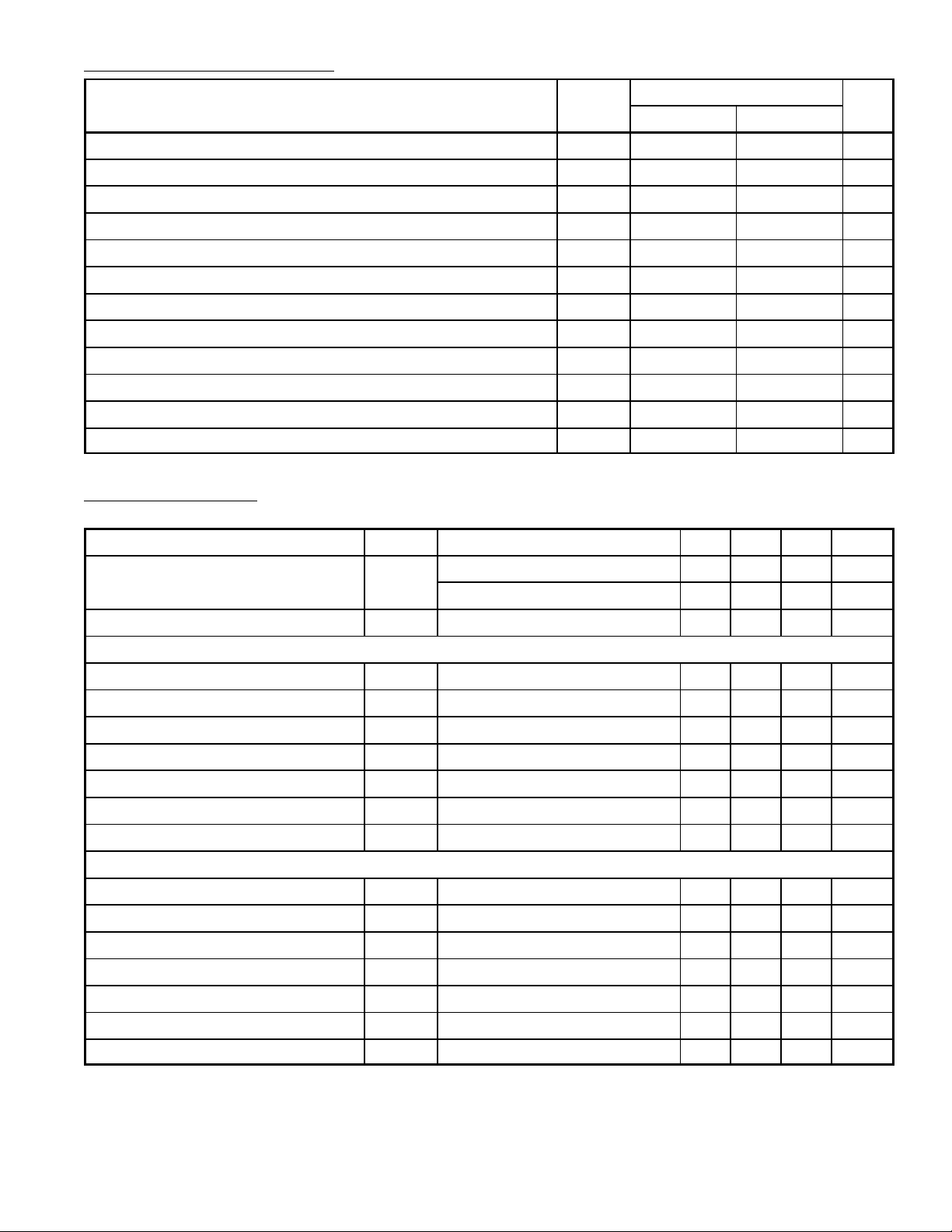
DC Characteristics (Cont’d): (VCC = 5V, Pin Voltage at No Signal)
Parameter Symbol
Typical
AM FM
Unit
Pin5 Voltage (AM IF Output) V
Pin6 Voltage (Meter Output) V
Pin7 Voltage (LED) V
Pin8 Voltage (GND) V
Pin9 Voltage (Detector Output) V
Pin10 Voltage (VCC) V
Pin11 Voltage (FM Detector) V
Pin12 Voltage (AM IF Bypass) V
Pin13 Voltage (AM IF Input) V
Pin14 Voltage (FM IF Bypass) V
Pin15 Voltage (FM IF Input) V
Pin16 Voltage (AM Mix Output) V
5
6
7
8
9
10
11
12
13
14
15
16
1.0 0.9 V
1.0 0.9 V
– – V
0 0 V
1.4 1.5 V
5.0 5.0 V
5.0 5.0 V
1.5 1.5 V
1.5 1.5 V
1.5 1.5 V
1.5 1.5 V
5.0 5.0 V
AC Characteristics: (VCC = 5V, TA = +25°C FM: f = 10.7MHz, ∆f = ±22.5kHz, fm = 400Hz
Parameter Symbol Test Conditions Min Typ Max Unit
Supply Current I
CC
AM: f = 1MHz, MOD = 30%, f
FM VIN = 0 – 10 15 mA
AM VIN = 0 – 7 10 mA
= 400Hz)
m
Pin5 Output Resistance R
f = 1kHz – 3.0 – kΩ
09
FM
Input Limiting Voltage V
Recovered Output Voltage V
IN(lim)
OD
–3dB Limiting – 40 46 dBµ
VIN = 66dBµV 57 85 114 mV
Signal–to–Noise Ratio S/N VIN = 80dBµV – 65 – dB
Total Harmonic Distortion THD VIN = 80dBµV – 0.05 – %
AM Rejection Ratio AMR VIN = 80dBµV – 38 – dBµ
Meter Drive Voltage V
Lamp ON Sensitivity V
VIN = 100dBµV – 1.8 – V
M
IL = 1mA – 46 52 dB
L
AM
Gain G
Recovered Output Voltage V
OD
VIN = 26dBµV 15 30 75 mV
V
VIN = 60dBµV 65 95 125 mV
Signal–to–Noise Ratio S/N VIN = 60dBµV – 47 – dB
Total Harmonic Distortion THD VIN = 60dBµV – 1.0 – %
Meter Drive Voltage V
Lamp ON Sensitivity V
Local OSC Stop Voltage V
stop
VIN = 100dBµV – 1.8 – V
M
IL = 1mA – 28 – dBµ
L
R
= ∞ – 1.5 – V
DUMP
rms
rms
rms
 Loading...