

NTE NTE1856, NTE1838 Datasheet
NTE1838 & NTE1856
Integrated Circuit
Color TV Video/Chroma/Deflection Circuit
Description:
The NTE1839 and NTE1856 are small–sized multifunctional integrated circuits containing the “video,
chroma, deflection” circuit of NTSC color TVs in a 30–Lead DIP type package. Besides being small–
sized, they have such features as fewer external components and fewer adjustments. required. The
NTE1838/NTE1856 can be used in conjunction with the NTE1728 for “VIFSIF” use or the
NTE1773/NTE1797 for “vertical output” use to perform all color TV signal processings.
The NTE1856 contains a peak clip circuit in the video circuit making it well suited for use in small–sized
TV sets while the NTE1838 contains no peak clip circuit and is suited for large–sized TV sets.
Features:
D Small–Sized Package
D Minimum Number of External Components Required
D Fewer Adjustments Required (Non–Adjusting of Functions Shown Below)
G Chroma VCO (APC)
G Horizontal OSC (H–Hold)
G Vertical OSC (V–Hold)
D Multifunctional
Absolute Maximum Ratings:
Maximum Supply Voltage, V
Maximum Supply Current, I
Allowable Power Dissipation (T
Operating Temperature Range, T
Storage Temperature Range, T
(TA = +25°C unless otherwise specified)
max 14V. . . . . . . . . . . . . . . . . . . . . . . . . . . . . . . . . . . . . . . . . . . . . . . . . . .
16
max 15mA. . . . . . . . . . . . . . . . . . . . . . . . . . . . . . . . . . . . . . . . . . . . . . . . . .
22
≤ +65°C), Pdmax 1100mW. . . . . . . . . . . . . . . . . . . . . . . . . . . . . . . . .
A
opr
stg
Recommended Operating Conditions:
Parameter Symbol Test Conditions Min Typ Max Unit
Recommended Supply Voltage V
Recommended Supply Current I
16
22
–20° to +85°C. . . . . . . . . . . . . . . . . . . . . . . . . . . . . . . . . . . . . . . . .
–55° to +125°C. . . . . . . . . . . . . . . . . . . . . . . . . . . . . . . . . . . . . . . . . .
(TA = +25°C unless otherwise specified)
9.0 12.0 14.0 V
8.5 10.0 15.0 mA
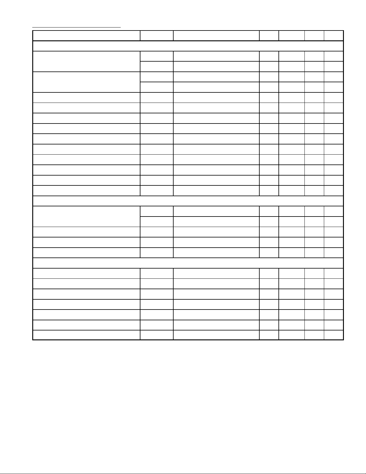
Electrical Characteristics: (TA = +25°C, V16 = 12V, I22 = 10mA unless otherwise specified)
Parameter Symbol Test Conditions Min Typ Max Unit
Chroma
ACC Amplitude Characteristic ACC
ACC Phase Characteristic ACC
ACC
ACC
1
2
Ø1
Ø2
Maximum B–Y Demodulation Output B–Ymax 5.0 – – V
–3 0 +3 dB
–7 0 +2 dB
– 0 ±3 deg
– 0 ±7 deg
PP
Unicolor Amplitude Characteristic ∆GU – 17 – dB
Tint Change Range ∆T – 110 – deg
APC Pull–In Range f
Color Difference Output DC Voltage E
Color Difference DC Difference Voltage E
APC
RGB
∆
RGB
±300 – –
6.7 7.2 7.7 V
– – ±300 mV
R–Y Relative Demodulation Angle ∠R–Y/B–Y – 104 – deg
G–Y Relative Demodulation Angle ∠G–Y/B–Y – –122 – deg
R–Y Demodulation Ratio R–Y/B–Y – 0.9 –
G–Y Demodulation Ratio G–Y/B–Y – 0.3 –
Video
Video Tone Control Characteristic GPmin –5 –3 –1 dB
GPmax 12 15 18 dB
Video Voltage Gain V
Contrast Variable Range ∆G
Frequency Response ∆G
Synchronization, Deflection
Sync Separation Input DC Level V
SS
Vertical Free–Running Frequency f
Vertical Blanking Pulse Width T
Vertical Drive Stage Voltage Gain V
Horizontal Free–Running Frequency f
Horizontal Drive Output Pulse Width T
Horizontal Sync Pull–In Range f
PULL
V
BL
H
G
C
f = 5MHz –5 – – dB
V
12 15 18 dB
– 18 – dB
– 9.3 – V
– fH/296.5 – Hz
– 19H –
G
– 16 – dB
– 15.734 – kHz
H
– 24.5 – µs
±400 – – Hz
 Loading...