

NTE NTE1837 Datasheet
NTE1837
Integrated Circuit
TV Tuner Controller
Description:
The NTE1837 i s a t uner c ontroller integrated c ircuit i n a 1 6–Lead DIP type p ackage c ontaining f unctions
such as band s witch, i nverter, and low–pass f ilter. T his d evice c an b e u sed a s a f requency s ynthesizer
or a voltage synthesizer, depending on the external application circuit.
Functions:
D Band Switch (Equivalent to the NTE1658: Refer to the Truth Table)
D Inverter
D Low–Pass Filter (Voltage Follower, Operational Amplifier)
Features:
D 2–Input, 5–Output Band Switch
D Band Switch (NTE1658) Available by Changing Over C Pin
D High Maximum Output Current, Low Saturation Voltage
D Meet CATV Tuner Requirements
D Frequency Synthesizer or Voltage Synthesizer Application depending on Inverter and
Operational Amplifier Connections
Absolute Maximum Ratings:
(TA = +25°C unless otherwise specified)
Band Switch
V
Maximum Supply Voltage, V16max 18V. . . . . . . . . . . . . . . . . . . . . . . . . . . . . . . . . . . . . . . . . . . . . .
CC1
V
Maximum Supply Current, I1max 10mA. . . . . . . . . . . . . . . . . . . . . . . . . . . . . . . . . . . . . . . . . . . . . .
CC2
Maximum Load Current
I
, I13max (I1 = 6mA) –60mA. . . . . . . . . . . . . . . . . . . . . . . . . . . . . . . . . . . . . . . . . . . . . . . . . . . . . .
12
I
, I15max (V
14
= 12V) –60mA. . . . . . . . . . . . . . . . . . . . . . . . . . . . . . . . . . . . . . . . . . . . . . . . . . .
CC1
I11max 25mA. . . . . . . . . . . . . . . . . . . . . . . . . . . . . . . . . . . . . . . . . . . . . . . . . . . . . . . . . . . . . . . . . . . .
Maximum AB Input Current, I
Maximum Applied Voltage (SW), V
, I3max 2mA. . . . . . . . . . . . . . . . . . . . . . . . . . . . . . . . . . . . . . . . . . . . . . . .
2
max 35V. . . . . . . . . . . . . . . . . . . . . . . . . . . . . . . . . . . . . . . . . . . . . .
11
Inverter, Operation Amplifier
V
Maximum Supply Voltage, V6max 35V. . . . . . . . . . . . . . . . . . . . . . . . . . . . . . . . . . . . . . . . . . . . . . .
CC3
V
Maximum Supply Current, I6max 5mA. . . . . . . . . . . . . . . . . . . . . . . . . . . . . . . . . . . . . . . . . . . . . . .
CC3
Maximum Applied Voltage, V
Maximum Load Current, I
Maximum Input Voltage, V
Maximum Input Current, I
max 35V. . . . . . . . . . . . . . . . . . . . . . . . . . . . . . . . . . . . . . . . . . . . . . . . . . . .
8
max 5mA. . . . . . . . . . . . . . . . . . . . . . . . . . . . . . . . . . . . . . . . . . . . . . . . . . . . . .
8
max 8V. . . . . . . . . . . . . . . . . . . . . . . . . . . . . . . . . . . . . . . . . . . . . . . . . . . . . . .
7
max 1mA. . . . . . . . . . . . . . . . . . . . . . . . . . . . . . . . . . . . . . . . . . . . . . . . . . . . . .
7
Maximum Input Voltage, V9max VCC –1V. . . . . . . . . . . . . . . . . . . . . . . . . . . . . . . . . . . . . . . . . . . . . . . . . .
Common to 1, 2
Allowable Power Dissipation (T
Operating Temperature Range, T
Storage Temperature Range, T
≤ +65°C), Pdmax 600mW. . . . . . . . . . . . . . . . . . . . . . . . . . . . . . . . . .
A
opr
stg
–20° to +65°C. . . . . . . . . . . . . . . . . . . . . . . . . . . . . . . . . . . . . . . . .
–55° to +125°C. . . . . . . . . . . . . . . . . . . . . . . . . . . . . . . . . . . . . . . . . .
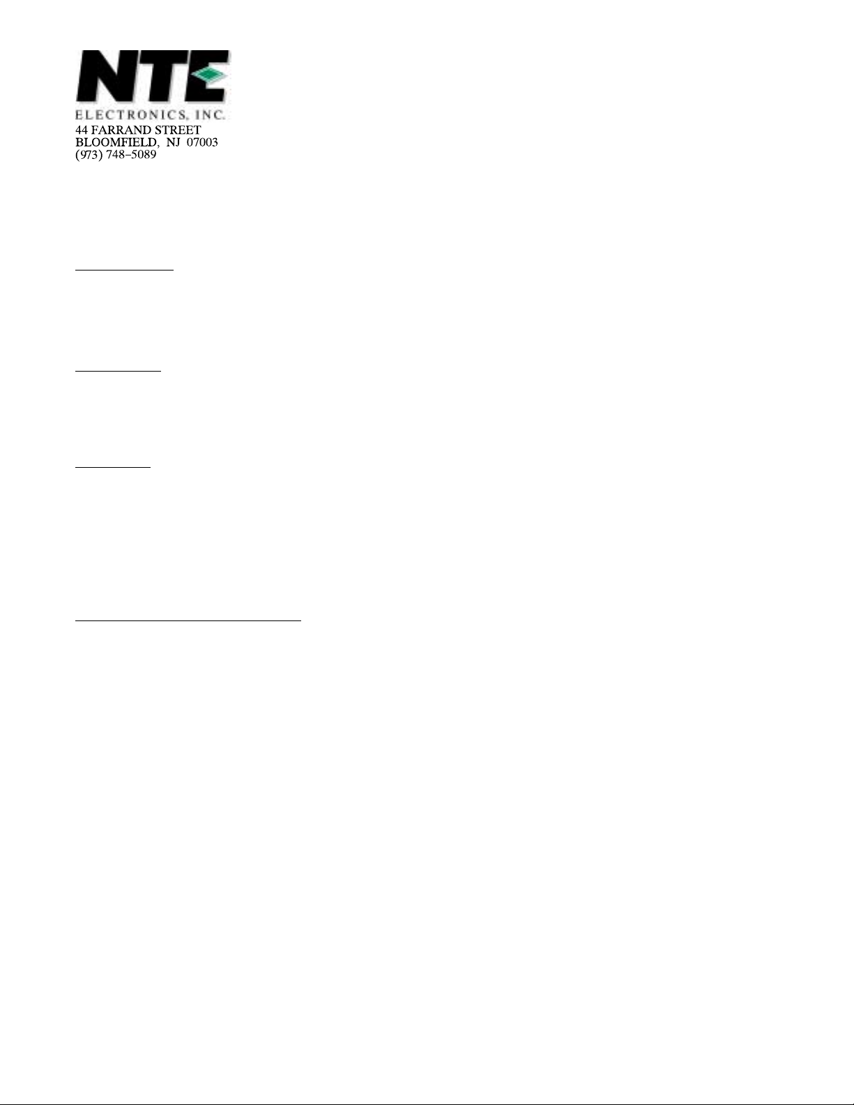
Operating Characteristics: (TA = +25°C unless otherwise specified)
Parameter Symbol Test Conditions Min Typ Max Unit
Band Switch
Quiescent Current I
CC
0 – 9 mA
Output Saturation Voltage F (sat) 0 – 0.7 V
SW (sat) 0 – 0.7 V
Input Threshold Voltage V
Output Leakage Current I
TH
L
0.8 1.5 3.0 V
0 – –50 µA
Inverter, Operational Amplifier, Zener
Output Saturation Voltage V
Input Threshold Voltage V
Input Offset Voltage V
V
Input Bias Current I
8 (sat)
TH
IO–1
IO–2
BIAS
0 – 0.3 V
2.5 – 4.5 V
–100 – +100 mV
–100 – +100 mV
– – –190 nA
Note 1. Current flowing into IC: Plus (No Sign)
Current flowing out of IC: Minus
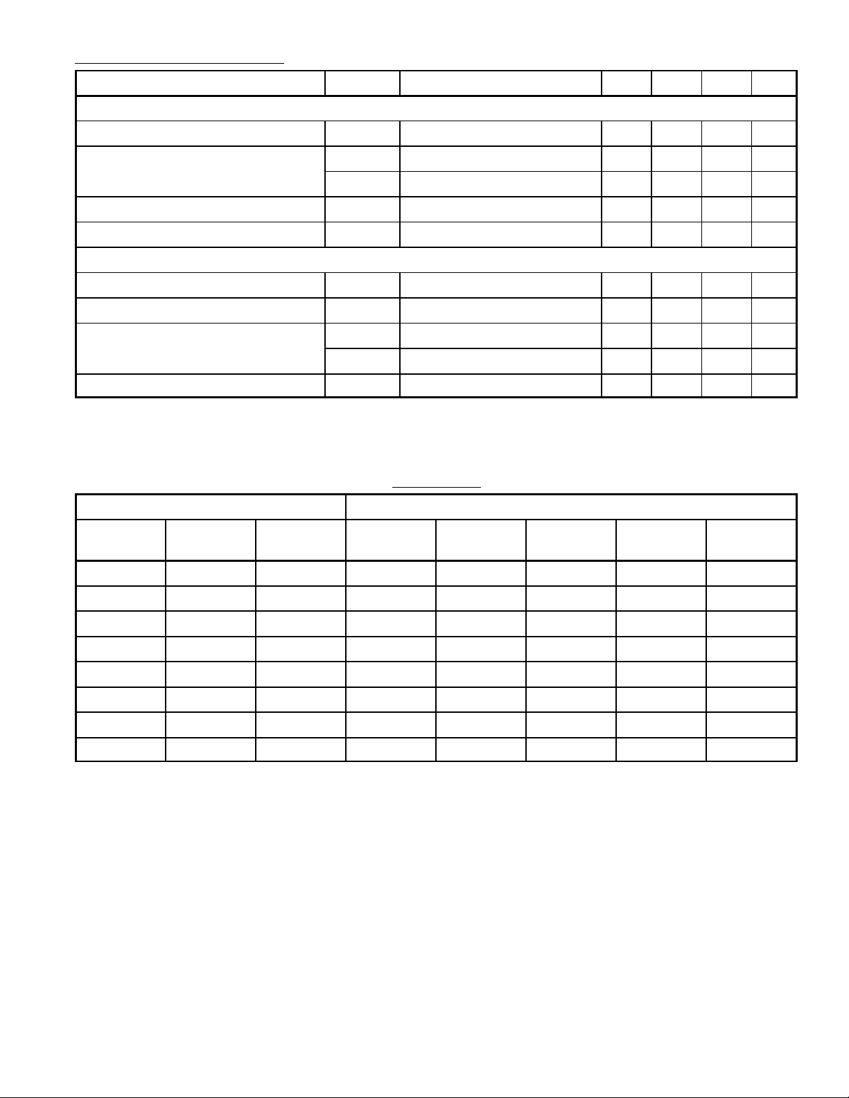
Truth Table
Input Output
A
(Pin3)
B
(Pin2)
C
(Pin4)
F1
(Pin15)
F2
(Pin14)
F3
(Pin13)
F4
(Pin12)
SW
(Pin11)
L L Open H Z Z Z Z
H L Open Z H Z Z L
L H Open Z Z H Z L
H H Open Z Z Z H L
L L GND H Z Z H Z
H L GND Z H Z H L
L H GND Z Z H Z L
H H GND Z Z H H L
Note 2. Z: High Impedance
 Loading...