

NTE NTE1807 Datasheet
Head Amplifier Circuit for 2 Head VCR
Features:
D Built–in Peaking Amplifier Circuit
NTE1807
Integrated Circuit
D Less Noise Voltage Referred to Input: 1µV
rms
Absolute Maximum Ratings: (TA = +25°C unless otherwise specified)
Supply Voltage, V
Power Dissipation (T
Operating Ambient Temperature, T
Storage Temperature Range, T
Electrical Characteristics:
Circuit Current I
Channel I Gain G
Channel II Gain G
AGC Output Amplitude υ
AGC Control Sensitivity ∆υ
PG Switch Changeover Sensitivity S
C
= +70°C), P
A
D
opr
stg
(TA = +25°C, VCC = 5V unless otherwise specified)
Parameter Symbol Test Conditions Min Typ Max Unit
1
3–9
5–9
12
f = 1MHz, 0.5mV
f = 1MHz, 0.5mV
f = 4MHz, 0.3mV
f = 4MHz, 0.3mV
20
f = 1MHz, 0.5mV
8
P–P
P–P
P–P
P–P
P–P
130mW. . . . . . . . . . . . . . . . . . . . . . . . . . . . . . . . . . . . . . . . . . . . . .
–20° to +70°C. . . . . . . . . . . . . . . . . . . . . . . . . . . . . . . . . . . . . . . .
–55° to +150°C. . . . . . . . . . . . . . . . . . . . . . . . . . . . . . . . . . . . . . . . . .
10 – 24 mA
52.5 – 62.5 dB
52.5 – 62.5 dB
154 – 286 mυ
– – 3 dB
– – 3.5 V
6V. . . . . . . . . . . . . . . . . . . . . . . . . . . . . . . . . . . . . . . . . . . . . . . . . . . . . . . . . . . . . . . . . .
P–P
Noise Voltage Referred to Input (I) V
Noise Voltage Referred to Input (II) V
Note 1. Operating Supply Voltage Range: V
ni1
ni2
CC(opr)
1MHz BFP – – 1 µV
1MHz BFP – – 1 µV
= 4.5 to 5.5V
rms
rms
Pin Connection Diagram
V
CC
Ch 1 Damping Adjust
Ch 1 Input
GND
14 8
1
2
3
4
5Ch 2 Input
6Ch 2 Damping Adjust
7PB ON Switch
14
Peaking
GND
13
AGC Output A
12
11
AGC Output B
10 AGC Level Detect
9 Chroma Signal Output
8 PG Pulse Input
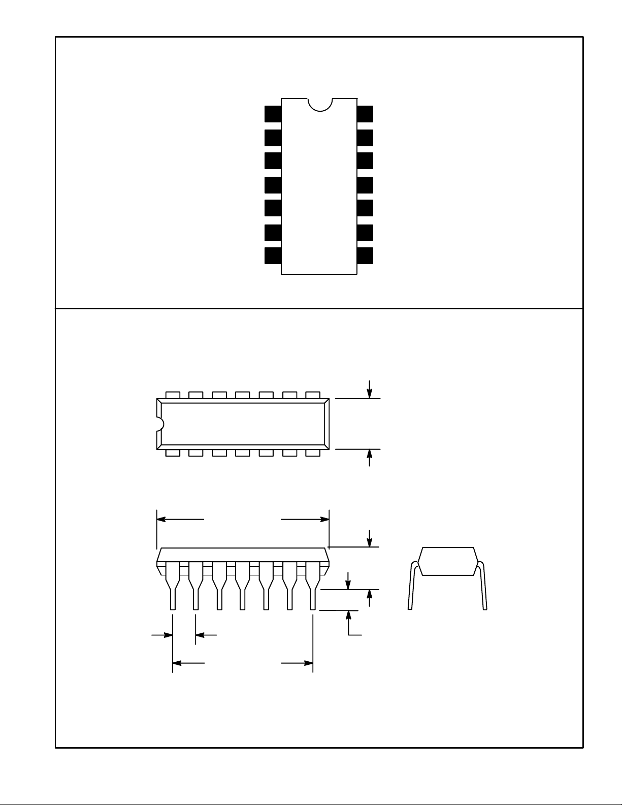
.250
(6.35)
17
.771 (19.06)
.185
(4.7)
.100 (2.54)
.120 (3.05)
.600 (15.24)
 Loading...