

NTE NTE1806 Datasheet
NTE1806
Integrated Circuit
Head Amplifier Circuit for 4 Head VCR
Features:
D Built–in Enveloped Comparing Circuit
D Built–in Peaking Amplifier Circuit
D Less Noise Voltage Referred to Input: 1µV
Absolute Maximum Ratings: (TA = +25°C unless otherwise specified)
Supply Voltage, V
Power Dissipation (T
Operating Ambient Temperature, T
Storage Temperature Range, T
C
= +70°C), P
A
D
opr
stg
Electrical Characteristics: (TA = +25°C, VCC = 5V unless otherwise specified)
Parameter Symbol Test Conditions Min Typ Max Unit
rms
6V. . . . . . . . . . . . . . . . . . . . . . . . . . . . . . . . . . . . . . . . . . . . . . . . . . . . . . . . . . . . . . . . . .
250mW. . . . . . . . . . . . . . . . . . . . . . . . . . . . . . . . . . . . . . . . . . . . . .
–20° to +70°C. . . . . . . . . . . . . . . . . . . . . . . . . . . . . . . . . . . . . . . .
–55° to +150°C. . . . . . . . . . . . . . . . . . . . . . . . . . . . . . . . . . . . . . . . . .
Circuit Current I
Channel I Gain G
Channel II Gain G
Channel III Gain G
Channel IV Gain G
AGC Output Amplitude υ
AGC Control Sensitivity υ
Head Switch Changeover Sensitivity S
Head Amp Switch Changeover Sensitivity S
Noise Voltage Referred to Input (I) V
Noise Voltage Referred to Input (II) V
Noise Voltage Referred to Input (III) V
Noise Voltage Referred to Input (IV) V
Envelope Comparative Output Amplitude υ
Envelope Comparative Output Stop Sensitivity S
Note 1. Operating Supply Voltage Range: V
16
3–15
4–15
8–15
9–15
20
20
1
11
ni3–15
ni4–15
ni8–15
ni9–15
14
17
CC(opr)
16 – 40 mA
f = 1MHz 50.5 – 60.5 dB
f = 1MHz 50.5 – 60.5 dB
f = 1MHz 50.5 – 60.5 dB
f = 1MHz 50.5 – 60.5 dB
f = 4MHz 100 – 190 mυ
f = 4MHz – – 3 dB
– – 1 V
– – 1 V
1MHz BFP – – 1 µV
1MHz BFP – – 1 µV
1MHz BFP – – 1 µV
1MHz BFP – – 1 µV
4.3 – – V
– – 1.2 V
= 4.5 to 5.5V
P–P
rms
rms
rms
rms
P–P
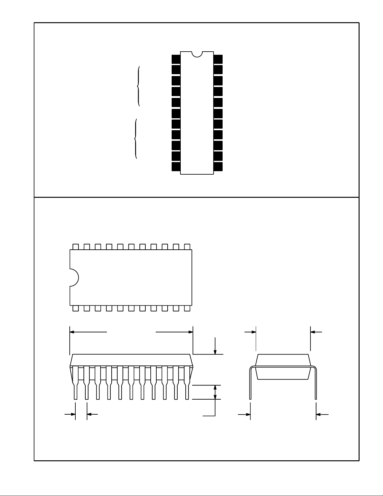
Pin Connection Diagram
Head Switch Changeover
Bias (I)
Input (I)
Initial Stage
Input (II)
Input Stage GND
Bias (III)
Initial Stage
Input (III)
Input (IV)
Bias (IV)
Head Amp Switch Changeover
1
2
3
4
5Bias (II)
6
7
8
22
21
20
19
18
17
16
15
9 14
10 13
11 12
AGC Control Signal Design
AGC Reverse Phase Output
AGC Output
Output Stage GND
Peaking Circuit Peak Constant
Envelope Comparative Circuit
Stop Switch
V
CC
Chroma Output
Envelope Comparative Output
Side Envelope Detection (III, IV)
Side Envelope Detection (I, II)
22 12
111
.756 (19.2) .252 (6.4)
.177
(4.5)
.300 (7.62).135 (3.43).070 (1.78)
 Loading...