

NTE NTE1799 Datasheet
NTE1799
Integrated Circuit
Electronics Switch for VCR & Audio Applications
Description:
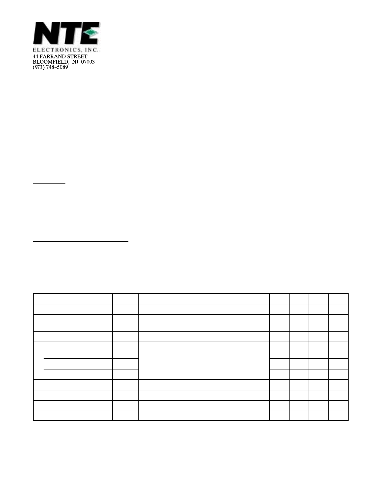
The NTE1799 is a 3–channel 2–position high–performance analog switch in a 16–Lead DIP type
package having wide applications from audio band to video band. It is also provided with 2 channels
of muting function.
Features:
D 3–Channel 2–Position Switch
D Wide Input Dynamic Range
D Low Distortion
D Good Frequency Characteristic
D Muting Available
Absolute Maximum Ratings
Maximum Supply Voltage, V
Allowable Power Dissipation (T
Operating Temperature Range, T
Storage Temperature Range, T
Operating Characteristics
Parameter Symbol Test Conditions Min Typ Max Unit
Current Dissipation I
Total Harmonic Distortion THD Rg = 600Ω, 4.5V
Noise Voltage V
Crosstalk
Ch1
Ch2 CR2
Ch3 CR3
Pedestal Level ∆V
Maximum Input Voltage VINmax Rg = 600Ω, f = 1kHz, RL = ∞, THD = 1%, Note 1 5.0 – – V
2nd Harmonic Voltage H2
3rd Harmonic Voltage H3 –46 –55 – dB
: (TA = +25°C unless otherwise specified)
CCmax
15V. . . . . . . . . . . . . . . . . . . . . . . . . . . . . . . . . . . . . . . . . . . . . . . . . . .
≤ +65°C), Pdmax 500mW. . . . . . . . . . . . . . . . . . . . . . . . . . . . . . . . . .
A
–20° to +65°C. . . . . . . . . . . . . . . . . . . . . . . . . . . . . . . . . . . . . . . . .
opg
–40° to +125°C. . . . . . . . . . . . . . . . . . . . . . . . . . . . . . . . . . . . . . . . . .
stg
: (TA = +25°C, VCC = 12V unless otherwise specified)
CC
N
CR1
pedVCTL
, f = 1kHz, RL = ∞, Note 1 – 0.0070.1 %
P–P
Rg = 600Ω, f = 20 to 20kHz, RL = ∞, Note 1 – –93 –80 dB
Input 1: Rg = 50Ω, 2V
f = 3.58MHz, Input 2: Rg = 500Ω,
Note 2
Note 2
(Pin10, Pin13, Pin15) = 0 to 12V, Note 1 –100 0 +100 mV
Rg = 50Ω, 4V
, f = 1MHz, RL = ∞, Note 1
P–P
P–P
,
– 30 39 mA
– –50 – dB
– –60 – dB
– –50 – dB
–46 –55 – dB
P–P
Note 1. Measurements are made for each of Ch1, Ch2, and Ch3 using input A and input B.
Input A: V
Input B: V
(Pin10, Pin13, Pin15) is 12V at the measurement mode.
CTL
is 0V at the measurement mode.
CTL
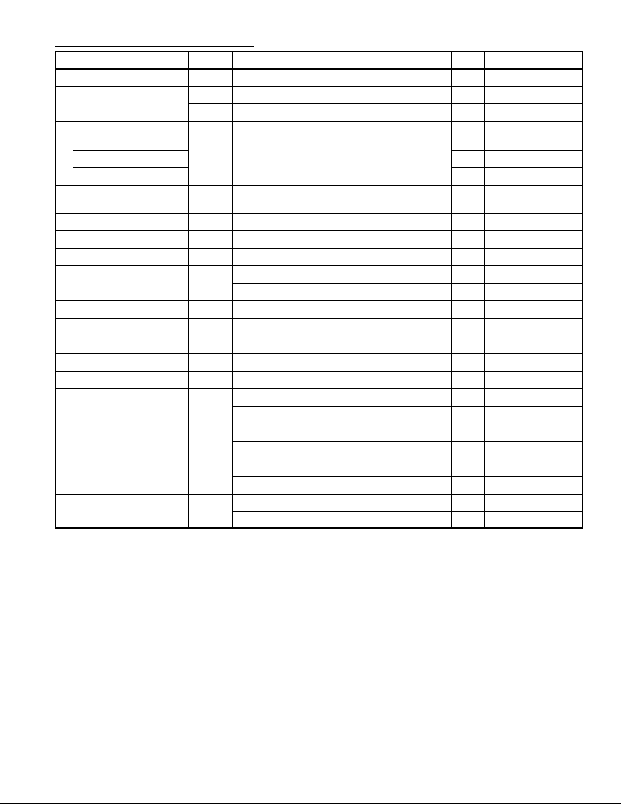
Operating Characteristics (Cont’d): (TA = +25°C, VCC = 12V unless otherwise specified)
Parameter Symbol Test Conditions Min Typ Max Unit
Switch Changeover Voltage V
Mute Threshold Voltage V
CTLs
V
Note 1 2.6 3.1 4.0 V
Low Level, Note 3 1.2 1.6 1.9 V
ML
High Level, Note 3 5.5 6.9 8.2 V
MH
Crosstalk Between Channels
Ch1
Ch2
Rg = 500Ω, RL = ∞,
Other channel input Rg = 50Ω, 2V
f = 3.58MHz, Note 4
f = 3.58MHz, Note 4
Ch3
Mute Compression Ratio Rg = 600Ω, 2V
Series Resistance 10kΩ, Note 3
Control Pin Flow–In Current I
Input Impedance z
Output Impedance z
Pin Voltage (Pin1) V
CTL
Note 1 – 3.8 – µA
Note 1 – 10 – kΩ
in
Note 1 – 29 – Ω
out
V15 = 0V – 7.9 – V
1
V15 = 12V – 7.9 – V
Pin Voltage (Pin2) V
Pin Voltage (Pin5) V
2
V13 = 0V – 7.9 – V
5
V13 = 12V – 7.9 – V
Pin Voltage (Pin6) V
Pin Voltage (Pin7) V
Pin Voltage (Pin8) V
6
7
V10 = 0V – 7.9 – V
8
V10 = 12V – 7.9 – V
, f = 1kHz, RL = ∞,
P–P
P–P
–50 –68 – dB
,
–50 –68 – dB
–50 –60 – dB
– –60 – dB
– 7.2 – V
– 7.2 – V
– 7.2 – V
Pin Voltage (Pin9) V
V10 = 0V – 7.9 – V
9
V10 = 12V – 7.9 – V
Pin Voltage (Pin12) V
V13 = 0V – 7.9 – V
12
V13 = 12V – 7.9 – V
Pin Voltage (Pin16) V
V15 = 0V – 7.9 – V
16
V15 = 12V – 7.9 – V
Note 1. Measurements are made for each of Ch1, Ch2, and Ch3 using input A and input B.
Input A: V
Input B: V
(Pin10, Pin13, Pin15) is 12V at the measurement mode.
CTL
is 0V at the measurement mode.
CTL
Note 2. Measurements are made using input A and input B.
Note 3. Measurements are made for Ch2, Ch3.
Note 4. Measurements are made for each of Ch1, Ch2, and Ch3 using input A and input B on other
channel.
 Loading...