

NTE NTE1785 Datasheet
NTE1785
Integrated Circuit
w
TV IF Amp
/Demod and AFC
(For PNP Tuners)
Description:
The NTE1785 is an IF amplifier and demodulator circuit in a 16–Lead DIP type package designed for
use in color and black and white television receivers using PNP tuners.
Features:
D Gain–Controlled Wide–Band Amplifier Providing Complete IF Gain
D Synchronous Demodulator
D White Spot Inverter
D Video Preamplifier with Noise Protection
D AFC Circuit which can be Switched ON/OFF by a DC Level (e.g. During Tuning)
D AGC Circuit with Noise Gating
D Tuner AGC Output (PNP Tuners)
D VCR Switch which Switches Off the Video Output (e.g. For Insertion of a VCR Playback Signal)
Absolute Maximum Ratings:
Supply Voltage, V
Tuner AGC Voltage, V
Total Power Dissipation, P
11–13
4–13
tot
Operating Ambient Temperature Range, T
Storage Temperature Range, T
stg
A
–25° to +60°C. . . . . . . . . . . . . . . . . . . . . . . . . . . . . . . . . . .
–55° to +125°C. . . . . . . . . . . . . . . . . . . . . . . . . . . . . . . . . . . . . . . . . .
13.2V. . . . . . . . . . . . . . . . . . . . . . . . . . . . . . . . . . . . . . . . . . . . . . . . . . . . . . . . . . . .
12V. . . . . . . . . . . . . . . . . . . . . . . . . . . . . . . . . . . . . . . . . . . . . . . . . . . . . . . . . . .
900mW. . . . . . . . . . . . . . . . . . . . . . . . . . . . . . . . . . . . . . . . . . . . . . . . . . . . .
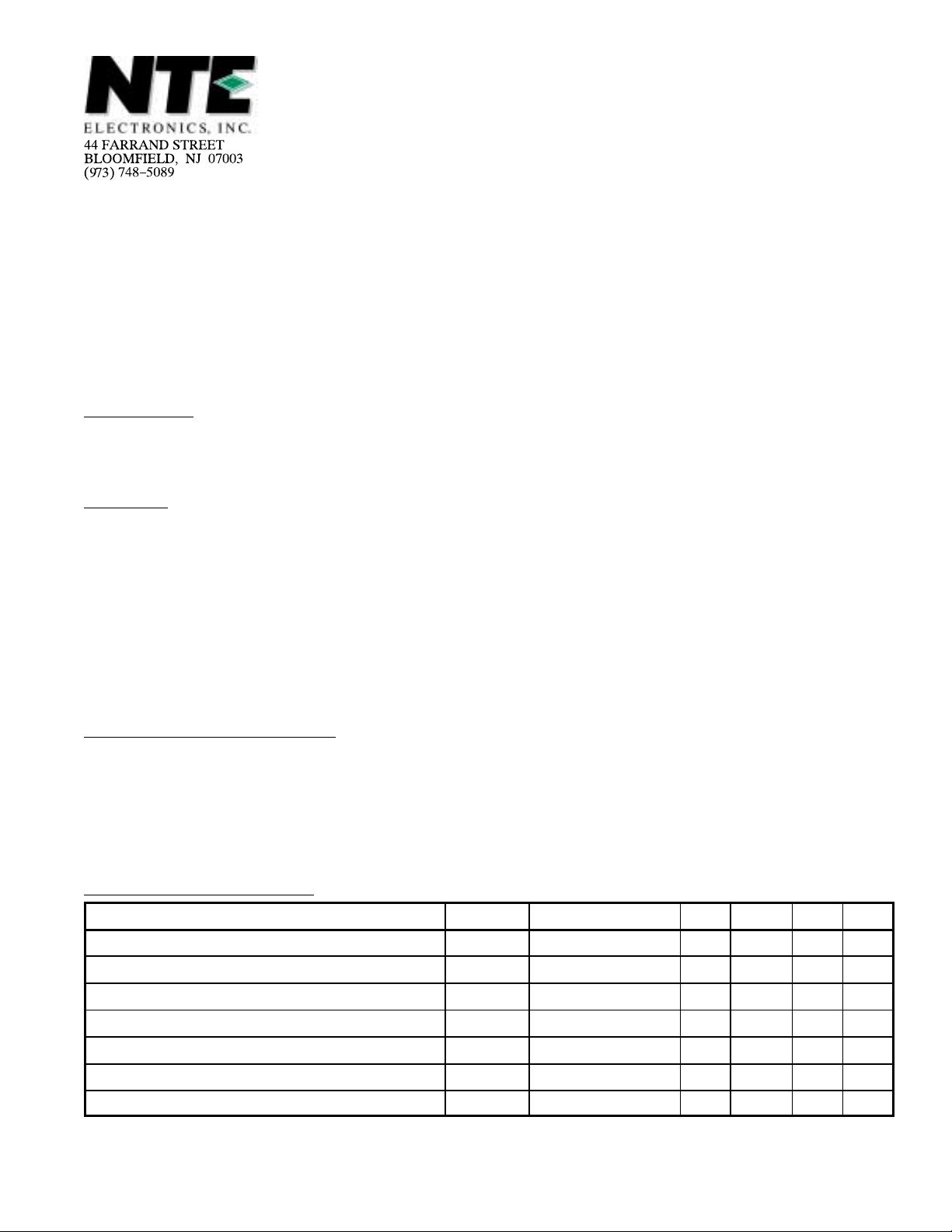
Electrical Characteristics:
Parameter Symbol Test Conditions Min Typ Max Unit
Supply Voltage Range V
IF Input Voltage for Onset of AGC (RMS Value) V
Differential Input Impedance |Z
Zero–Signal Output Level V
Top Sync Output Level V
IF Voltage Gain Control Range G
Bandwidth of Video Amplifier B 3dB – 6 – MHz
(TA = +25°C, V
= 12V, f = 38.9MHz unless otherwise specified)
11–13
11–13
1–16(rms)
| In parallel with 2pF – 2 – kΩ
1–16
12–13
12–13
V
Note 1 – 6 ±0.3 – V
10.2 12.0 13.2 V
– 100 150 µV
2.9 3.07 3.2 V
– 64 – dB
Note 1. So–called “Projected Zero Point”, e.g. with switched demodulator.
Electrical Characteristics (Cont’d): (TA = +25°C, V
= 12V, f = 38.9MHz unless otherwise
11–13
specified)
Parameter Symbol Test Conditions Min Typ Max Unit
Signal–to–Noise Ratio S/N Vi = 10mV, Note 2 – 58 – dB
Differential Gain dG – 4 10 %
Differential Phase – 2 10 deg.
Intermodulation, Blue 1.1MHz, Note 3 – 46 60 dB
Intermodulation, Yellow
Intermodulation 3.3MHz, Note 4 – 46 54 dB
Carrier Signal at Video Output – 4 30 mV
2nd Harmonic of Carrier at Video Output – 20 30 mV
White Spot Inverter Threshold Level – 6.6 – V
White Spot Insertion Level – 4.7 – V
Noise Inverter Threshold Level – 1.8 – V
Noise Insertion Level – 3.8 – V
– 46 50 dB
External Video Switch (VCR) Switched Off V
Tuner AGC Output Current Range I
Tuner AGC Output Voltage V
Tuner AGC Output Leakage Current I
Maximum AFC Output Voltge Swing ∆V
14–13
4
4–13
4
5–13
I4 = 10mA – – 0.3 V
V
14–13
= 11V, V
= 12V – – 15 µA
4–13
– – 1.1 V
0 – 10 mA
10 11 – V
Detuning for AFC Output Voltage Swing ∆f of 10V – 100 200 kHz
AFC Zero–Signal Output Voltage
V
5–13
4 6 8 V
(Minumum Gain)
AFC Switches ON V
AFC Switches OFF V
Note 2. S/N = VO black–to–white/V
Note 3. 20 log (V
Note 4. 20 log (V
at 4.4MHz/VO at 1.1MHz) + 3.6dB.
O
at 4.4MHz/VO at 3.3MHz)
O
n(rms)
6–13
6–13
at B = 5MHz.
3.2 – – V
– – 1.5 V
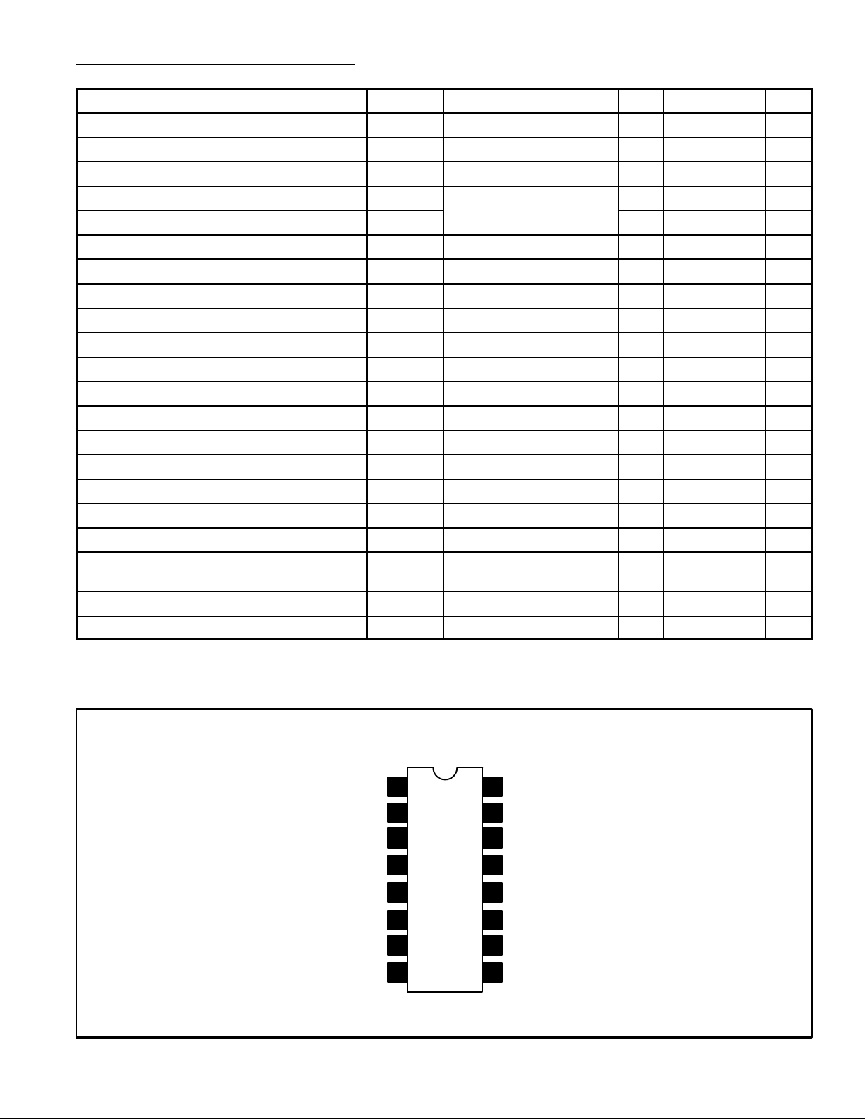
Pin Connection Diagram
IF Input
Coupling Cap
1
2
16
IF Input
Coupling Cap
15
AGC Delay Input
AGC Output GND
AFC Output
AFC Switch Input
AFC Tank (Sync)
AFC Tank (Amp)
3
4
5
6
7
8
14
AGC Filter
13
12
Video Output
V
11
CC
10
AFC Tank (Sync)
9
AFC Tank (Amp)
 Loading...