

NTE NTE1771 Datasheet
NTE1771
Integrated Circuit
TV Video Processor
Description:
The NTE1771 is a small–sized multifunctional IC containing the “video, chroma, deflection” circuit of
NTSC color TV in a shrink type 30–Lead DIP package. Besides being small–sized, it has such features as greately reduced number of parts and fewer adjustments required. The device contains no
peak clip circuit and is well suited for use in large–sized sets.
Features:
D Small–Sized Package
D Minimum Number of Parts Required
D Fewer Adjustments Required
D Chroma VCO (APC)
D Horizontal OSC (H–Hold)
D Vertical OSC (V–Hold)
D Multifunction
Absolute Maximum Ratings: (TA = +25°C unless otherwise specified)
Maximum Supply Voltage, V
Maximum Supply Current, I
Allowable Power Dissipation (TA ≤ +65°C), P
Operating Temperature Range, T
Storage Temperature Range, T
16(max)
22(max)
stg
opg
D(max)
–20° to +85°C. . . . . . . . . . . . . . . . . . . . . . . . . . . . . . . . . . . . . . . . .
–55° to +125°C. . . . . . . . . . . . . . . . . . . . . . . . . . . . . . . . . . . . . . . . . .
Recommended Operating Conditions: (TA = +25°C unless otherwise specified)
Recommended Supply Voltage, V
Recommended Supply Current, I
16
22
Operating Voltage Range 9 to 14V. . . . . . . . . . . . . . . . . . . . . . . . . . . . . . . . . . . . . . . . . . . . . . . . . . . . . . .
Operating Current Range 0.5 to 15.0mA. . . . . . . . . . . . . . . . . . . . . . . . . . . . . . . . . . . . . . . . . . . . . . . . . .
14V. . . . . . . . . . . . . . . . . . . . . . . . . . . . . . . . . . . . . . . . . . . . . . . . . . .
15.0mA. . . . . . . . . . . . . . . . . . . . . . . . . . . . . . . . . . . . . . . . . . . . . . . . .
1100mW. . . . . . . . . . . . . . . . . . . . . . . . . . . . . . . . .
12V. . . . . . . . . . . . . . . . . . . . . . . . . . . . . . . . . . . . . . . . . . . . . . . . . .
10mA. . . . . . . . . . . . . . . . . . . . . . . . . . . . . . . . . . . . . . . . . . . . . . . . .
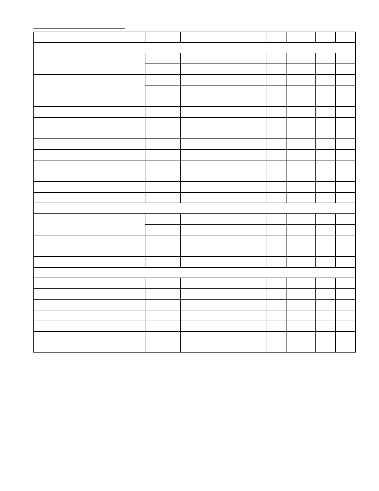
Electrical Characteristics: (TA = +25°C, V16 = 12V, I22 = 10mA unless otherwise specified)
Parameter Symbol Test Conditions Min Typ Max Unit
Chroma
ACC Amplitude Characteristics ACC1 –3 0 +3 dB
ACC2 –7 0 +2 dB
ACC Phase Characteristics ACC∅1 – 0 ±3 deg
ACC∅2 – 0 ±7 deg
Maximum B–Y Demodulation Output B–Y max 5.0 – – V
P–P
Unicolor Amplitude Characteristics ∆GU – 17 – dB
Tint Change Range ∆T – 110 – deg
APC Pull–In Range f
Color Difference Output DC Voltage E
Color Difference DC Difference Voltage E
APC
RGB
∆
RGB
±300 – –
6.7 7.2 7.7 V
– – ±300 mV
R–Y Relative Demodulation Angle ∠R–Y/B–Y – 104 – deg
G–Y Relative Demodulation Angle ∠G–Y/B–Y – –122 – deg
R–Y Demodulation Ratio R–Y/B–Y – 0.9 –
G–Y Demodulation Ratio G–Y/B–Y – 0.3 –
Video
Video Tone Control Characteristics Gpmin –5 –3 –1 dB
Gpmax 12 15 18 dB
Video Voltage Gain VG 12 15 18 dB
Contrast Variable Range ∆GC – 18 – B
Frequency Response ∆GV f = 5MHz –5 – – dB
Synchronization, Deflection
Sync Separation Input DC Level V
Vertical Free–Running Frequency f
Vertical Blanking Pulse Width T
S.S
V
BL
– 9.3 – V
– fH/296.5 – Hz
– 19H –
Vertical Drive Stage Voltage Gain VG – 16 – dB
Horizontal Free–Running Frequency f
Horizontal Drive Output Pulse Width T
Horizontal Sync Pull–In Range f
PULL
H
H
– 15.734 – kHz
– 24.5 – µs
±400 – – Hz
 Loading...