

NTE1737
Integrated Circuit
Module, Chopper & Chopper Parallel
w
/2–Output Voltage Regulator
Features:
D 2 Outputs for Miicrocomputer Power Supply (5V) and Motor Drive Power Supply (24V) and
Capable of Delivering 2 Regulated Voltage Outputs from 1 Rectifier
D Independent Overcurrent Protectors for 2 Outputs (Foldback Characteristics)
Applications:
D Serial Printers, Line Printers, Office Automation Equipment
D Floppy Disk Units, Portable VCRs
Absolute Maximum Ratings: (TA = +25°C unless otherwise specified)
Maximum DC Input Voltage, VIN (DC) max 50V. . . . . . . . . . . . . . . . . . . . . . . . . . . . . . . . . . . . . . . . . . . .
Maximum Output Current, IOmax
Average 3A. . . . . . . . . . . . . . . . . . . . . . . . . . . . . . . . . . . . . . . . . . . . . . . . . . . . . . . . . . . . . . . . . . . . . .
Peak
VO1 3.6A. . . . . . . . . . . . . . . . . . . . . . . . . . . . . . . . . . . . . . . . . . . . . . . . . . . . . . . . . . . . . . . . . . . .
VO2 6.0A. . . . . . . . . . . . . . . . . . . . . . . . . . . . . . . . . . . . . . . . . . . . . . . . . . . . . . . . . . . . . . . . . . . .
Operating Case Temperature, T
Junction Temperature, T
J
Storage Temperature Range, T
C
stg
Thermal Resistance, Junction–to–Case, R
VO1 4.7°C/W. . . . . . . . . . . . . . . . . . . . . . . . . . . . . . . . . . . . . . . . . . . . . . . . . . . . . . . . . . . . . . . . . . . .
VO2 2.7°C/W. . . . . . . . . . . . . . . . . . . . . . . . . . . . . . . . . . . . . . . . . . . . . . . . . . . . . . . . . . . . . . . . . . . .
–30° to +105°C. . . . . . . . . . . . . . . . . . . . . . . . . . . . . . . . . . . . . . . . . .
thJC
+105°C. . . . . . . . . . . . . . . . . . . . . . . . . . . . . . . . . . . . . . . . . . . . . . . . . .
+150°C. . . . . . . . . . . . . . . . . . . . . . . . . . . . . . . . . . . . . . . . . . . . . . . . . . . . . . . . .
Absolute Maximum Ratings: (TA = +25°C unless otherwise specified)
Parameter Test Conditions VO1 VO2 Unit
Output Voltage Condition 1 5 ±0.1 24 ±0.1 V
Ripple Voltage Condition 1 5 20 mV
Line Regulation Condition 2 15 30 mV/V Max
Load Regulation Condition 3 70 50 mV/V Max
Overcurrent Trip Start Current Condition 4 3.6 6.0 A Min
Effeciency Condition 5 80 80 % Typ
Operating Frequency Condition 1 35 35 kHz Typ
Cutoff Voltage Condition 1 – 3V or more ON
– 1V or less OFF
Temperature Coefficient Condition 1 –0.025 –0.01 %/°C
rms
Max
Test Conditions:
Condition 1: VIN (DC) = 35V, IO1 = IO2 = 1A
Condition 2: VIN (DC) = 30V to 40V, IO1 = IO2 = 1A
Condition 3: VIN (DC) = 35V, IO1 = 1A to 3.6A, IO2 = 1A to 6A
Condition 4: VIN (DC) = 35V
Condition 5: VIN (DC) = 35V, IO1 = IO2 = 1.5A
Pin Connection Diagram
(Front View)
18 N.C.
17
VIN 1
16
VIN 1
15
VIN 2
14
VIN 2
13
V
Z
Sense GND
12
Output 2
11
Output 210
GND
9
GND
8
Output 1
7
6 Output 1
V1 Sense 1
5
V1 Sense 2
4
V2 Sense 1
3
V2 Sense 22
Cutoff
1
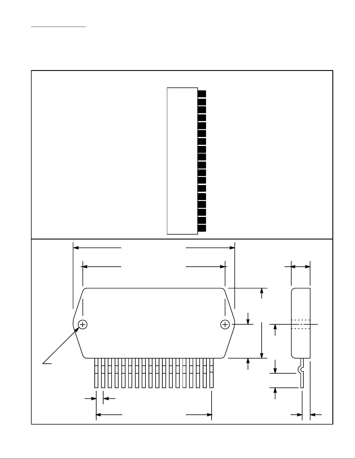
.141
(3.6)
Dia
(2 Holes)
2.520 (64.0)
2.190 (55.6)
.334 (8.5)
1.440
(36.4)
.737
(18.7)
118
1.030
(32.5)
.158 (4.0)
.100 (2.54)
.114 (5.5)1.700 (43.18)
 Loading...