

NTE1708
Integrated Circuit
TV Tuner Band Selector
Description:
This NTE1708 is a tuner band selector integrated circuit in a 9–Lead SIP type package intended for
use in electronic tuning type TV sets. This device outputs supply voltages to the tuner unit according
to 2–input band select signals.
Features:
D 2 Inputs, 4 Outputs
D Decoders of 2 Types Available by Changing–Over C Pin.
D Single–Supply Operation (Output Transistor: PNP Type)
D Low Output Saturation Voltage
Absolute Maximum Ratings: (TA = +25°C unless otherwise specified)
Maximum Supply Voltage, VCCmax 14V. . . . . . . . . . . . . . . . . . . . . . . . . . . . . . . . . . . . . . . . . . . . . . . . . . .
Maximum Applied Voltage, V6, V
7
Maximum Load Current
IO6max (f1) –20mA. . . . . . . . . . . . . . . . . . . . . . . . . . . . . . . . . . . . . . . . . . . . . . . . . . . . . . . . . . . . . . .
IO1max (f2) –35mA. . . . . . . . . . . . . . . . . . . . . . . . . . . . . . . . . . . . . . . . . . . . . . . . . . . . . . . . . . . . . . .
IO7max (f3) –20mA. . . . . . . . . . . . . . . . . . . . . . . . . . . . . . . . . . . . . . . . . . . . . . . . . . . . . . . . . . . . . . .
IO2max (f4) –35mA. . . . . . . . . . . . . . . . . . . . . . . . . . . . . . . . . . . . . . . . . . . . . . . . . . . . . . . . . . . . . . .
Input Current, IINmax 2mA. . . . . . . . . . . . . . . . . . . . . . . . . . . . . . . . . . . . . . . . . . . . . . . . . . . . . . . . . . . . . .
Allowable Power Dissipation, PDmax 400mA. . . . . . . . . . . . . . . . . . . . . . . . . . . . . . . . . . . . . . . . . . . . . .
Operating Temperature Range, T
Storage Temperature Range, T
stg
opr
–20° to +65°C. . . . . . . . . . . . . . . . . . . . . . . . . . . . . . . . . . . . . . . . .
–55° to +125°C. . . . . . . . . . . . . . . . . . . . . . . . . . . . . . . . . . . . . . . . . .
–12V. . . . . . . . . . . . . . . . . . . . . . . . . . . . . . . . . . . . . . . . . . . . . . . . . . .
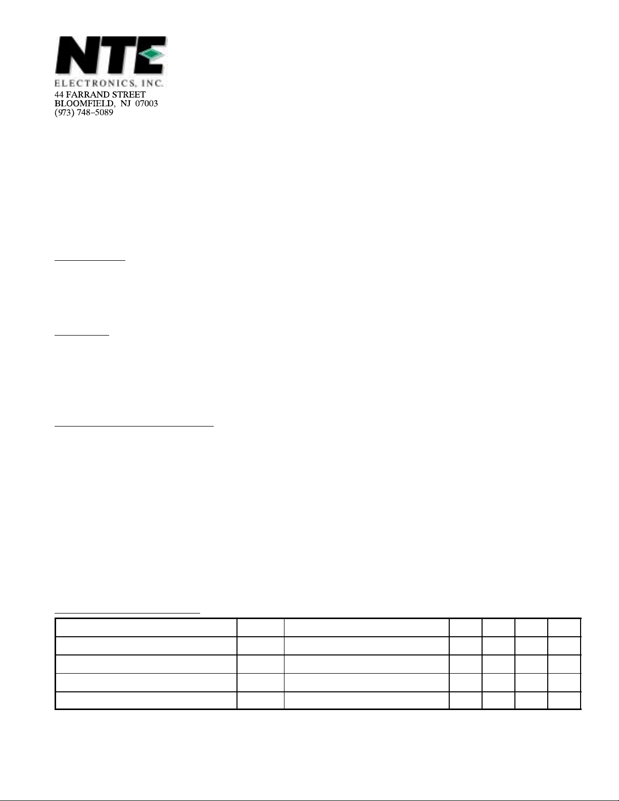
Electrical Characteristics: (TA = +25°C unless otherwise specified)
Parameter Symbol Test Conditions Min Typ Max Unit
Quiescent Current I
Output Saturation Voltage 0 – 0.7 V
Input Threshold Voltage V
Output Leakage Current I6, I
CCO
TH
7
– 13 18 mA
0.8 1.5 3.0 V
– – 50 µA
Note 1. Current flowing into IC: + (no sign)
Note 2. Current flowing out of IC: –
Truth Table:
Input Control Pin Output
A (Pin3) B (Pin4) C (Pin8) f1 (Pin6) f2 (Pin1) f3 (Pin7) f4 (Pin2)
H H V
L H V
H L V
L L V
H H Open H Z Z H
L H Open Z Z H H
H L Open Z H Z Z
L L Open H Z H H
CC
CC
CC
CC
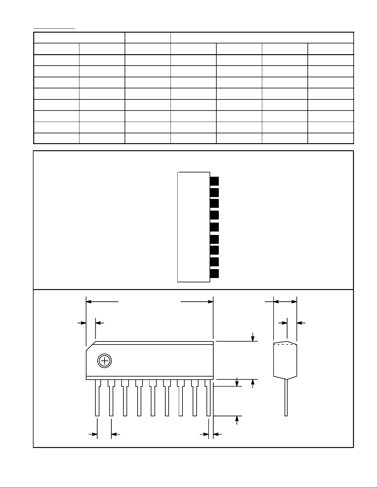
Pin Connection Diagram
Z Z Z H
Z Z H H
Z H Z Z
H Z H H
(Front View)
9
V
CC
Bootstrap
8
Ripple Filter
7
Ripple Filter
6
Input
5
Negative Feedback
4
Phase Compensation
3
GND
2
Output
1
.862 (21.89) .118 (3.0)
.059 (1.5)
.053(1.35)
.177
(4.5)
19
.110
(2.8)
.100 (2.54) .031 (0.78)
 Loading...