

NTE1701
Integrated Circuit
VCR Cylinder Servo Control Circuit
Features:
D Phase Control Circuit
D Speed Control Circuit
D CTL Amplifier
D Capstan PG Amplifier
D Sample Hold Type Speed Control
D Supply Voltage Either 9V or 12V
Absolute Maximum Ratings: (TA = +25°C unless otherwise specified)
Supply Voltage, V
Power Dissipation (TA = +70°C), P
Operating Ambient Temperature Range, T
Storage Temperature Range, T
Electrical Characteristics: (TA = +25°C ±2°C, VCC = 12V unless otherwise specified)
Parameter Symbol Test Conditions Min Typ Max Unit
1–7
stg
D
opr
–20° to +70°C. . . . . . . . . . . . . . . . . . . . . . . . . . . . . . . . . .
–40° to +150°C. . . . . . . . . . . . . . . . . . . . . . . . . . . . . . . . . . . . . . . . . .
14.4V. . . . . . . . . . . . . . . . . . . . . . . . . . . . . . . . . . . . . . . . . . . . . . . . . . . . . . . . . . . . . .
880mW. . . . . . . . . . . . . . . . . . . . . . . . . . . . . . . . . . . . . . . . . . . . . . .
Circuit Current I
PG (–) Amp Input Sensitivity S
PG (+) Amp Input Sensitivity S
Cap PG Amp Input Sensitivity S
VSS Amp Input Sensitivity S
REC/PB Select Sensitivity V
Phase System Trapezoidal Wave
Reference Voltage
Head SW Output Voltage, High V
Head SW Output Voltage, Low V
REC CTL Amp Output Voltage, High V
REC CTL Amp Output Voltage, Low V
S/H 1 Output Voltage, High V
S/H 1 Output Voltage, Low V
V
20–H
20–L
6–H
6–L
15–H
15–L
1
24
23
3
25
28
17
V
Vi Pin23 1V
Pin24 2V
Pin23 2V
Note 1. Operating supply voltage range, V
= 12V 33 – 65 mA
1–7
1 – – V
1 – – V
50 – – mV
2 – – V
5 – – V
2.7 – 3.7 V
9 – – V
– – 600 mV
8 – – V
– – 1 V
9 – – V
– – 600 mV
CC(opr)
, Vi Pin24 30Hz, Duty 4%
O–P
30Hz, Duty 96%,
P–P
30Hz, Duty 4%
P–P
= 8.8V to 13V.
O–P
O–P
O–P
O–P
Electrical Characteristics (Cont’d): (TA = +25°C ±2°C, VCC = 12V unless otherwise specified)
Parameter Symbol Test Conditions Min Typ Max Unit
CTL Amp Gain B
FG Amp Input Sensitivity S
Speed System Trapezoidal
Reference Voltage
S/H 2 Output Voltage, High V
S/H 2 Output Voltage, Low V
Cap PG Output Voltage, High V
Cap PG Output Voltage, Low V
V
2
14
10
8–H
8–L
2–H
2–L
Note 1. Operating supply voltage range, V
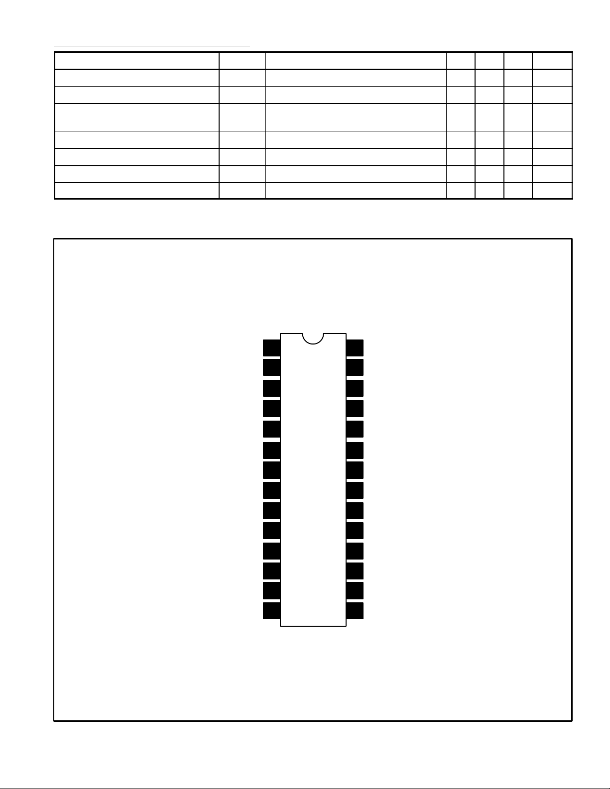
Pin Connection Diagram
CC
1
V
CC(opr)
= 8.8V to 13V.
28
REC/PB Select
62 – 70 dB
100 – – mV
2.7 – 3.7 V
10 – – V
– – 1.8 V
44 – 6.6 V
– – 600 mV
P–P
Cap PG Output
Cap PG Input
Control Amp
Feedback
GND
Control Output
& Input
Sample & Hold
Output
Sample & Hold
Capacitance
Trapezoid Reference
Trapezoid Cap
GND
Speed Mono Multi
Cylinder FG Input
2
3
4
5
6
7GND
8
9
10
11
13
14
27
1/2 VSS Mono Multi
26
N.C.
25
VSS Input
PG Input (–)
24
23
PG Input (+)
PG Mono Multi
22
PG Mono Multi
21
20
Head Switch Output
REC Shifter Mono Multi
19
Trapezoid Output
18
Trapezoid Reference12 17
Sample & Hold
16
Capacitance
15
Sample & Hold Output

14 1
15 28
1.469 (37.32) Max
.100 (2.54)
1.300 (33.02)
.250
(6.35)
.122
(3.1)
Min
.540
(13.7)
.600
(15.24)
 Loading...