

NTE NTE1673 Datasheet

NTE1673
Integrated Circuit
Video Chroma Processor
Description:
The NTE1673 is a multifunctional integrated circuit in a 28–Lead DIP type package where an APC
chroma circuit is formed so compactly as to use only 16 pins with the characteristic requirements remaining fulfilled and the rest of pins are used for video circuits. It contains a double doefferential circuit
enabling soft video tone, a color temperature control circuit enabling reproduction of beautiful bright
white color and true color, and a high level contrast circuit elinimating brightness drop at the time of
contrast adjustment, thereby allowing a wider design margin for television set design engineers.
Functions:
D Band–Pass Amp
D Voltage Controlled Oscillation
D Peak Clip
D Color Saturation Control
D Double Differential
D Killer
D Contrast Amp
D Color Temperature Control
D Tint Control
D DC Restoration
D Automatic Saturation Control
D Automatic Phase Control
D Blanking
D Chroma Demodulation
D Bright Control
Functions:
D High level contrast system eliminating brightness drop at the time of contrast adjustment.
D Double differential circuit enabling soft video tone.
D Color temperature control function enabling reproduction of beautiful bright white color and
true color
D Capable of being connected to IC for VIR.
D Only one adjustement: APC adjustment
D Minimum number of external parts required.
Absolute Maximum Ratings
Maximum Supply Voltage, V
Allowable Power Dissipation (T
Operating Temperature Range, T
Storage Temperature Range, T
: (TA = +25°C unless otherwise specified)
max 14.5V. . . . . . . . . . . . . . . . . . . . . . . . . . . . . . . . . . . . . . . . . . . . . . . . .
CC
≤ +65°C), PDmax 875mW. . . . . . . . . . . . . . . . . . . . . . . . . . . . . . . . . .
A
opr
stg
–20° to +70°C. . . . . . . . . . . . . . . . . . . . . . . . . . . . . . . . . . . . . . . . .
–40° to +125°C. . . . . . . . . . . . . . . . . . . . . . . . . . . . . . . . . . . . . . . . . .
Electrical Characteristics: (TA = +25°C, VCC = 12V, 0dB input: burst 100mV
unless otherwise specified)
Parameter Symbol Test Conditions Min Typ Max Unit
Chroma Characteristics
, chroma 200mV
p–p
p–p
ACC Amplitude Characteristic G
ACC Phase Characteristic φA +6dB – 0 ±3 deg
Killer Operating Point V
Maximum B–Y Demodulation Θ
Tint Change Range ∆T(T
Static Phase Error φΘ ∆f = ±100Hz ±1.5 ±5 – deg
APC Pull–in Range f
Demodulation Output DC Voltage V12, V13, V
Demodulation Output DC V12 – V
Video Characteristics
Video Tone Control G
Video Gain G
Contrast Variable Range ∆G
Frequency Characteristic ∆G
A
i(K)
OBM
max–Tmin
p
13
p max
G
p min
v
C
V
+6dB –7 0 ±3 dB
–20dB – –3 +2 dB
–20dB – ±3 ±7 deg
–55 –47 –40 dB
4.5 5.5 – V
) – 120 – deg
±350 ±500 – H
14
f = 5MHz –3 – – dB
6.7 7.2 7.7 V
– 300 – mV
7.0 9.5 12.0 dB
–5.0 –2.5 –1.0 dB
10 12.5 15.0 dB
8 10 12 dB
p–p
z
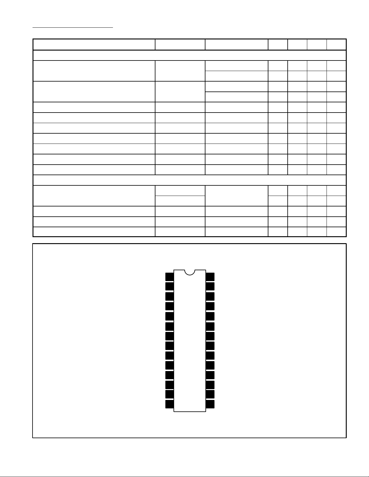
Pin Connection Diagram
Video Input
Color Control
ACC Detector
V
CC
Killer RC Network
X’tal
APC Control
R – Y Demodulation
G – Y Matrix
B – Y Demodulation
1
2
3
4
5
6GND
7Tint Control
8
9Tint Network 20
10Demod Network
11
13
14
Video Tone Control
28
Sharp Video Tone
27
Network
Sharp Video Tone
26
Network
Soft Video Tone
25
Network
24
Contrast Control
High Level Contrast
23
Control
22
DC Restorer Network
21
Brightness Control
Horiz Sync Output
19
Brightness Sample
18
Horiz Blank Pulse
Color Temp Control12 17
Horiz Sync Input
16
15
Video Output Driver
 Loading...