

NTE NTE1670 Datasheet

NTE1670
Integrated Circuit
Air Core Meter Driver
Description:
The NTE1670 is a function generator/driver for air–core (moving–magnet) meter movements in a
14–Lead DIP type package. A Norton amplifier and an NPN transistor are included on chip for signal
conditioning as required. Driver outputs are self–centering and develop ± 4.5V swing at 20mA. Better
than 2% linearity is guaranteed over a full 305–degree operating range.
Features:
D Self–Centering 20mA Outputs
D 12V Operation
D Norton Amplifier
D Function Generator
Applications:
D Air–Core Meter Driver
D Tachometers
D Ruggedized Instruments
Absolute Maximum Ratings:
Supply Voltage (Pin13), V
Power Dissipation (Note 1), P
Collector–Emitter Breakdown Voltage, V
Operating Temperature Range, T
Storage Temperature Range, T
CC
D
(BR)CEO
opr
stg
. . . . . . . . . . . . . . . . . . . . . . . . . . . . . . . . . . . . .
Lead Temperature (During soldering, 10sec Max), T
–40°C to +85°C. . . . . . . . . . . . . . . . . . . . . . . . . . . . . . . . . . . . . . .
–65°C to –150°C. . . . . . . . . . . . . . . . . . . . . . . . . . . . . . . . . . . . . . . .
L
1300mW. . . . . . . . . . . . . . . . . . . . . . . . . . . . . . . . . . . . . . . . . . . . . . . . . .
20V
+260°C. . . . . . . . . . . . . . . . . . . . . . . . . . . . . . . .
20V. . . . . . . . . . . . . . . . . . . . . . . . . . . . . . . . . . . . . . . . . . . . . . . . . . . . . . . . .
MIN
Note 1 For operation above +25°C, the NTE1670 must be derated based upon a +125°C maximum
junction temperature and a thermal resistance of +76°C/W which applies for the device sol-
dered in a printed circuit board and operating in a still–air ambient.
Electrical Characteristics: (VCC = 13.1V TA = +25°C unless otherwise specified)
Parameter Symbol Test Conditions Min Typ Max Unit
Supply Current (Pin13) I
Regulator Voltage (Pin11) V
Regulator Output Resistance (Pin11) I
REGIREG
Zero Input Frequency – – 65 mA
S
= 0mA 8.1 8.5 8.9 V
= 0mA to 3mA – 13.5 – Ω
REG
Electrical Characteristics (Cont’d): (VCC = 13.1V TA = +25°C unless otherwise specified)
Parameter Symbol Test Conditions Min Typ Max Unit
Reference Voltage (Pin4) V
REFIREF
Reference Output Resistance (Pin4) I
Norton Amplifier Mirror Gain(Pin5, Pin6) I
NPN Transistor DC Gain (Pin9, Pin10) h
FE
Function Generator Feedback Bias Current
= 0mA 1.9 2.1 2.3 V
= 0µA to 50µA – 5.3 – kΩ
REF
^ 20µA 0.9 1.0 1.1
BIAS
– 125 –
V1 = 5.1V – 1.0 – mA
(Pin1)
Drive Voltage Extremes, Sine and Cosine
I
= 20mA ±4.0 ±4.5 – V
LOAD
(Pin2, Pin12)
Sine Output Voltage with Zero Input (Pin2) V8 = V
REF
–350 0 +350 mV
Function Generator Linearity FSD = 305° – – ±1.7 %FSD
Function Generator Gain k Meter Deflection/∆V
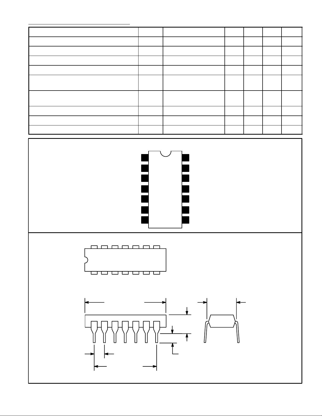
Pin Connection Diagram
N.C.
N.C.
1
2
3
4
14
GND
13
V
CC
12
Cosine Output
11
8.5V Reg
Common
Sine Output
50.75 53.75 56.75 °/V
8
5Inverting Input
6Non–Inverting Input
7GND
14 8
17
.785 (19.95)
Max
10 Signal Input
9 Pulse Train
8 Norton Amp Out
.200 (5.08)
Max
.300
(7.62)
.100 (2.45) .099 (2.5) Min
.600 (15.24)
 Loading...